Dell PowerEdge T300 Hardware Owner's Manual (PDF) - Page 117
Installing the Processor, Ensure that the release lever on the processor socket is fully extended, or
 |
View all Dell PowerEdge T300 manuals
Add to My Manuals
Save this manual to your list of manuals |
Page 117 highlights
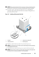
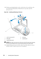
Installing the Processor 1 Unpack the new processor. 2 Ensure that the release lever on the processor socket is fully extended, or in the up position (see Figure 3-28). 3 Align the processor with the socket keys on the ZIF socket (see Figure 3-28). NOTICE: Positioning the processor incorrectly can permanently damage the system board or the processor when you turn it on. When placing the processor in the socket, be careful not to bend the pins in the socket. Avoid touching the socket pins or the pads on the processor when handling the processor or the system board. NOTICE: Do not use force to seat the processor. When the processor is positioned correctly, it engages easily into the socket. 4 With the processor and the socket keys aligned, set the processor lightly in the socket. 5 When the processor is fully seated in the socket, close the processor cover (see Figure 3-28). 6 Rotate the socket release lever back down until it snaps into place, securing the processor (see Figure 3-28). 7 Install the heat sink. NOTE: If you did not receive a replacement heat sink, re-use the heat sink that you removed from the old processor. a If you receive a heat sink and pre-applied thermal grease with your processor kit, remove the protective sheet from the thermal grease layer on top of the heat sink. If you did not receive a replacement heat sink with your processor kit, do the following: • Using a clean lint-free cloth, remove the thermal grease from the heat sink removed from the old processor. • Open the grease packet included with your processor kit and apply thermal grease evenly to the top of the new processor (see Figure 3-27). Installing System Components 117
-
 1
1 -
2
-
3
-
4
-
5
-
6
-
7
-
8
-
9
-
10
-
11
-
12
-
13
-
14
-
15
-
16
-
17
-
18
-
19
-
20
-
21
-
22
-
23
-
24
-
25
-
26
-
27
-
28
-
29
-
30
-
31
-
32
-
33
-
34
-
35
-
36
-
37
-
38
-
39
-
40
-
41
-
42
-
43
-
44
-
45
-
46
-
47
-
48
-
49
-
50
-
51
-
52
-
53
-
54
-
55
-
56
-
57
-
58
-
59
-
60
-
61
-
62
-
63
-
64
-
65
-
66
-
67
-
68
-
69
-
70
-
71
-
72
-
73
-
74
-
75
-
76
-
77
-
78
-
79
-
80
-
81
-
82
-
83
-
84
-
85
-
86
-
87
-
88
-
89
-
90
-
91
-
92
-
93
-
94
-
95
-
96
-
97
-
98
-
99
-
100
-
101
-
102
-
103
-
104
-
105
-
106
-
107
-
108
-
109
-
110
-
111
-
 112
112 -
 113
113 -
 114
114 -
 115
115 -
 116
116 -
 117
117 -
 118
118 -
 119
119 -
 120
120 -
 121
121 -
 122
122 -
123
-
124
-
125
-
126
-
127
-
128
-
129
-
130
-
131
-
132
-
133
-
134
-
135
-
136
-
137
-
138
-
139
-
140
-
141
-
142
-
143
-
144
-
145
-
146
-
147
-
148
-
149
-
150
-
151
-
152
-
153
-
154
-
155
-
156
-
157
-
158
-
159
-
160
-
161
-
162
-
163
-
164
-
165
-
166
-
167
-
168
-
169
-
170
-
171
-
172
-
173
-
174
-
175
-
176
-
177
-
178
-
179
-
180
-
181
-
182
-
183
-
184
-
185
-
186
-
187
-
188
-
189
-
190
-
191
-
192
-
193
-
194
 |
 |
