Dell PowerEdge T610 Hardware Owner's Manual - Page 102
Internal USB Memory Key - dimensions
 |
View all Dell PowerEdge T610 manuals
Add to My Manuals
Save this manual to your list of manuals |
Page 102 highlights
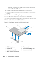
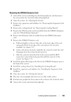
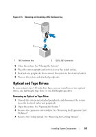
2 Open the system. See "Opening the System." 3 Remove the expansion card stabilizer. See "Removing the Expansion Card Stabilizer." 4 Remove the cooling shroud. See "Removing the Cooling Shroud." 5 Insert the tabs on the internal USB module in the slots in the chassis, and slide it into the slots until it the module release tab locks into place. See Figure 3-12. 6 Route the internal USB module cable through the cable guides in the chassis, and connect it to the INT_USB connector labeled on the system board. See Figure 6-1 for the connector location. 7 Install the cooling shroud. See "Installing the Cooling Shroud." 8 Install the expansion card stabilizer. See "Installing the Expansion Card Stabilizer." 9 Close the system. See "Closing the System." 10 Place the system upright and on its feet on a flat, stable surface. 11 Reattach any peripherals, then connect the system to the electrical outlet. 12 Turn on the system and attached peripherals. Internal USB Memory Key An optional USB memory key installed inside your system can be used as a boot device, security key, or mass storage device. The USB connector must be enabled by the Internal USB Port option in the Integrated Devices screen of the System Setup program. See "Using the System Setup Program and UEFI Boot Manager." To boot from the internal USB memory key, configure the USB memory key with a boot image and then specify the USB memory key in the boot sequence in the System Setup program. NOTE: Maximum dimensions supported for the USB memory key are 24-mm (.95-in) wide, 79-mm (3.1-in) long, and 8.6-mm (.34-in) deep. 1 Turn off the system and attached peripherals, and disconnect the system from the electrical outlet and peripherals. 2 Open the system. See "Opening the System." 102 Installing System Components
-
 1
1 -
2
-
3
-
4
-
5
-
6
-
7
-
8
-
9
-
10
-
11
-
12
-
13
-
14
-
15
-
16
-
17
-
18
-
19
-
20
-
21
-
22
-
23
-
24
-
25
-
26
-
27
-
28
-
29
-
30
-
31
-
32
-
33
-
34
-
35
-
36
-
37
-
38
-
39
-
40
-
41
-
42
-
43
-
44
-
45
-
46
-
47
-
48
-
49
-
50
-
51
-
52
-
53
-
54
-
55
-
56
-
57
-
58
-
59
-
60
-
61
-
62
-
63
-
64
-
65
-
66
-
67
-
68
-
69
-
70
-
71
-
72
-
73
-
74
-
75
-
76
-
77
-
78
-
79
-
80
-
81
-
82
-
83
-
84
-
85
-
86
-
87
-
88
-
89
-
90
-
91
-
92
-
93
-
94
-
95
-
96
-
 97
97 -
 98
98 -
 99
99 -
 100
100 -
 101
101 -
 102
102 -
 103
103 -
 104
104 -
 105
105 -
 106
106 -
 107
107 -
108
-
109
-
110
-
111
-
112
-
113
-
114
-
115
-
116
-
117
-
118
-
119
-
120
-
121
-
122
-
123
-
124
-
125
-
126
-
127
-
128
-
129
-
130
-
131
-
132
-
133
-
134
-
135
-
136
-
137
-
138
-
139
-
140
-
141
-
142
-
143
-
144
-
145
-
146
-
147
-
148
-
149
-
150
-
151
-
152
-
153
-
154
-
155
-
156
-
157
-
158
-
159
-
160
-
161
-
162
-
163
-
164
-
165
-
166
-
167
-
168
-
169
-
170
-
171
-
172
-
173
-
174
-
175
-
176
-
177
-
178
-
179
-
180
-
181
-
182
-
183
-
184
-
185
-
186
-
187
-
188
-
189
-
190
-
191
-
192
-
193
-
194
-
195
-
196
-
197
-
198
-
199
-
200
-
201
-
202
-
203
-
204
-
205
-
206
 |
 |