Dell PowerEdge T610 Hardware Owner's Manual - Page 138
Control Panel Assembly, Removing the Control Panel Assembly - release date
 |
View all Dell PowerEdge T610 manuals
Add to My Manuals
Save this manual to your list of manuals |
Page 138 highlights
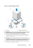
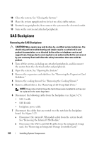
11 Reconnect the control panel cable to the CTRL_PNL connector on the system board. 12 Install the expansion-card stabilizer bracket: Fit the slots on the bracket over the metal guides in the chassis, and slide the bracket downwards until the release latch locks into place. See Figure 3-27. 13 Install the integrated storage controller card. See "Installing an Integrated Storage Controller Card." 14 Install the cooling shroud. See "Installing the Cooling Shroud." 15 Install the expansion card stabilizer. See "Installing the Expansion Card Stabilizer." 16 Close the system. See "Closing the System." 17 Place the system upright and on its feet on a flat, stable surface. 18 Reattach any peripherals, then connect the system to the electrical outlet. 19 Turn on the system and attached peripherals. 20 Enter the System Setup program to confirm that the battery is operating properly. See "Entering the System Setup Program." 21 Enter the correct time and date in the System Setup program's Time and Date fields, and specify other system configuration settings. 22 Exit the System Setup program. Control Panel Assembly Removing the Control Panel Assembly CAUTION: Many repairs may only be done by a certified service technician. You should only perform troubleshooting and simple repairs as authorized in your product documentation, or as directed by the online or telephone service and support team. Damage due to servicing that is not authorized by Dell is not covered by your warranty. Read and follow the safety instructions that came with the product. 1 Turn off the system, including any attached peripherals, and disconnect the system from the electrical outlet and peripherals. 2 Open the system. See "Opening the System." 138 Installing System Components
-
 1
1 -
2
-
3
-
4
-
5
-
6
-
7
-
8
-
9
-
10
-
11
-
12
-
13
-
14
-
15
-
16
-
17
-
18
-
19
-
20
-
21
-
22
-
23
-
24
-
25
-
26
-
27
-
28
-
29
-
30
-
31
-
32
-
33
-
34
-
35
-
36
-
37
-
38
-
39
-
40
-
41
-
42
-
43
-
44
-
45
-
46
-
47
-
48
-
49
-
50
-
51
-
52
-
53
-
54
-
55
-
56
-
57
-
58
-
59
-
60
-
61
-
62
-
63
-
64
-
65
-
66
-
67
-
68
-
69
-
70
-
71
-
72
-
73
-
74
-
75
-
76
-
77
-
78
-
79
-
80
-
81
-
82
-
83
-
84
-
85
-
86
-
87
-
88
-
89
-
90
-
91
-
92
-
93
-
94
-
95
-
96
-
97
-
98
-
99
-
100
-
101
-
102
-
103
-
104
-
105
-
106
-
107
-
108
-
109
-
110
-
111
-
112
-
113
-
114
-
115
-
116
-
117
-
118
-
119
-
120
-
121
-
122
-
123
-
124
-
125
-
126
-
127
-
128
-
129
-
130
-
131
-
132
-
 133
133 -
 134
134 -
 135
135 -
 136
136 -
 137
137 -
 138
138 -
 139
139 -
 140
140 -
 141
141 -
 142
142 -
 143
143 -
144
-
145
-
146
-
147
-
148
-
149
-
150
-
151
-
152
-
153
-
154
-
155
-
156
-
157
-
158
-
159
-
160
-
161
-
162
-
163
-
164
-
165
-
166
-
167
-
168
-
169
-
170
-
171
-
172
-
173
-
174
-
175
-
176
-
177
-
178
-
179
-
180
-
181
-
182
-
183
-
184
-
185
-
186
-
187
-
188
-
189
-
190
-
191
-
192
-
193
-
194
-
195
-
196
-
197
-
198
-
199
-
200
-
201
-
202
-
203
-
204
-
205
-
206
 |
 |