Dell PowerEdge T610 Hardware Owner's Manual - Page 142
SAS Backplane, Removing the SAS Backplane - usb 3 supported
 |
View all Dell PowerEdge T610 manuals
Add to My Manuals
Save this manual to your list of manuals |
Page 142 highlights
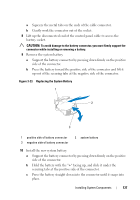
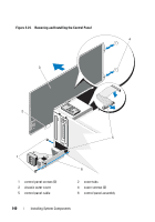
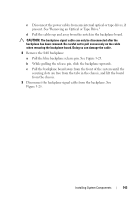
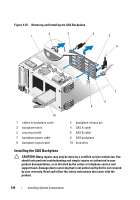
10 Close the system. See "Closing the System." 11 Place the system upright and on its feet on a flat, stable surface. 12 Reattach any peripherals, then connect the system to the electrical outlet. 13 Turn on the system and attached peripherals. SAS Backplane Removing the SAS Backplane CAUTION: Many repairs may only be done by a certified service technician. You should only perform troubleshooting and simple repairs as authorized in your product documentation, or as directed by the online or telephone service and support team. Damage due to servicing that is not authorized by Dell is not covered by your warranty. Read and follow the safety instructions that came with the product. 1 Turn off the system, including any attached peripherals, and disconnect the system from the electrical outlet and peripherals. 2 Open the system. See "Opening the System." 3 Remove the expansion card stabilizer. See "Removing the Expansion Card Stabilizer." 4 Remove the cooling shroud. See "Removing the Cooling Shroud." 5 Remove all hard drives. See "Removing a Hot-Swap Hard Drive." NOTE: Keep note of which bays the hard drives were installed in so they can be replaced in the same bays later. 6 Disconnect the following cables from the backplane (see Figure 3-25): • SAS A cable • SAS B cable • backplane power cable 7 Disconnect the cables that are routed over the notch in the backplane board. See Figure 3-25. a Disconnect the internal USB module cable from the system board. See "Removing the Internal USB Module." b Disconnect the SAS A and SAS B cables from the integrated storage card. See "Removing an Integrated Storage Controller Card." 142 Installing System Components
-
 1
1 -
2
-
3
-
4
-
5
-
6
-
7
-
8
-
9
-
10
-
11
-
12
-
13
-
14
-
15
-
16
-
17
-
18
-
19
-
20
-
21
-
22
-
23
-
24
-
25
-
26
-
27
-
28
-
29
-
30
-
31
-
32
-
33
-
34
-
35
-
36
-
37
-
38
-
39
-
40
-
41
-
42
-
43
-
44
-
45
-
46
-
47
-
48
-
49
-
50
-
51
-
52
-
53
-
54
-
55
-
56
-
57
-
58
-
59
-
60
-
61
-
62
-
63
-
64
-
65
-
66
-
67
-
68
-
69
-
70
-
71
-
72
-
73
-
74
-
75
-
76
-
77
-
78
-
79
-
80
-
81
-
82
-
83
-
84
-
85
-
86
-
87
-
88
-
89
-
90
-
91
-
92
-
93
-
94
-
95
-
96
-
97
-
98
-
99
-
100
-
101
-
102
-
103
-
104
-
105
-
106
-
107
-
108
-
109
-
110
-
111
-
112
-
113
-
114
-
115
-
116
-
117
-
118
-
119
-
120
-
121
-
122
-
123
-
124
-
125
-
126
-
127
-
128
-
129
-
130
-
131
-
132
-
133
-
134
-
135
-
136
-
 137
137 -
 138
138 -
 139
139 -
 140
140 -
 141
141 -
 142
142 -
 143
143 -
 144
144 -
 145
145 -
 146
146 -
 147
147 -
148
-
149
-
150
-
151
-
152
-
153
-
154
-
155
-
156
-
157
-
158
-
159
-
160
-
161
-
162
-
163
-
164
-
165
-
166
-
167
-
168
-
169
-
170
-
171
-
172
-
173
-
174
-
175
-
176
-
177
-
178
-
179
-
180
-
181
-
182
-
183
-
184
-
185
-
186
-
187
-
188
-
189
-
190
-
191
-
192
-
193
-
194
-
195
-
196
-
197
-
198
-
199
-
200
-
201
-
202
-
203
-
204
-
205
-
206
 |
 |