Dell PowerEdge T610 Hardware Owner's Manual - Page 110
Open the system. See Opening the System., See
 |
View all Dell PowerEdge T610 manuals
Add to My Manuals
Save this manual to your list of manuals |
Page 110 highlights
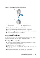
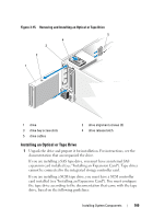
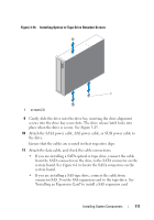
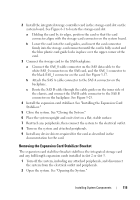
a Each device attached to a SCSI host adapter must have a unique SCSI ID number (narrow SCSI devices use IDs 0 to 7; wide SCSI devices use IDs from 0 to 15). Set the drive's SCSI ID to avoid conflicts with other devices on the SCSI bus. For the default SCSI ID setting, see the documentation provided with the drive. NOTE: There is no requirement that SCSI ID numbers be assigned sequentially or that devices be attached to the cable in order by ID number. b SCSI logic requires that the two devices at opposite ends of a SCSI chain be terminated and that all devices in between be unterminated. Enable the tape drive's termination if it is the last device in a chain of devices (or sole device) connected to the SCSI controller. 2 Turn off the system and attached peripherals, and disconnect the system from the electrical outlet and peripherals. 3 Open the system. See "Opening the System." 4 Remove the expansion card stabilizer. See "Removing the Expansion Card Stabilizer." 5 Remove the cooling shroud. See "Removing the Cooling Shroud." 6 To remove an old drive or drive blank, slide the drive release latch in the direction of the arrow to release the shoulder screws, and slide the drive or drive blank out to remove it from the drive bay. See Figure 3-15. 7 Remove the three shoulder screws from the old drive or the drive blank. See Figure 3-16. 8 On the new drive, attach one of the shoulder screws to the top row of holes and two to the bottom row of holes. See Figure 3-16. 110 Installing System Components
-
 1
1 -
2
-
3
-
4
-
5
-
6
-
7
-
8
-
9
-
10
-
11
-
12
-
13
-
14
-
15
-
16
-
17
-
18
-
19
-
20
-
21
-
22
-
23
-
24
-
25
-
26
-
27
-
28
-
29
-
30
-
31
-
32
-
33
-
34
-
35
-
36
-
37
-
38
-
39
-
40
-
41
-
42
-
43
-
44
-
45
-
46
-
47
-
48
-
49
-
50
-
51
-
52
-
53
-
54
-
55
-
56
-
57
-
58
-
59
-
60
-
61
-
62
-
63
-
64
-
65
-
66
-
67
-
68
-
69
-
70
-
71
-
72
-
73
-
74
-
75
-
76
-
77
-
78
-
79
-
80
-
81
-
82
-
83
-
84
-
85
-
86
-
87
-
88
-
89
-
90
-
91
-
92
-
93
-
94
-
95
-
96
-
97
-
98
-
99
-
100
-
101
-
102
-
103
-
104
-
 105
105 -
 106
106 -
 107
107 -
 108
108 -
 109
109 -
 110
110 -
 111
111 -
 112
112 -
 113
113 -
 114
114 -
 115
115 -
116
-
117
-
118
-
119
-
120
-
121
-
122
-
123
-
124
-
125
-
126
-
127
-
128
-
129
-
130
-
131
-
132
-
133
-
134
-
135
-
136
-
137
-
138
-
139
-
140
-
141
-
142
-
143
-
144
-
145
-
146
-
147
-
148
-
149
-
150
-
151
-
152
-
153
-
154
-
155
-
156
-
157
-
158
-
159
-
160
-
161
-
162
-
163
-
164
-
165
-
166
-
167
-
168
-
169
-
170
-
171
-
172
-
173
-
174
-
175
-
176
-
177
-
178
-
179
-
180
-
181
-
182
-
183
-
184
-
185
-
186
-
187
-
188
-
189
-
190
-
191
-
192
-
193
-
194
-
195
-
196
-
197
-
198
-
199
-
200
-
201
-
202
-
203
-
204
-
205
-
206
 |
 |