Dell PowerEdge T610 Hardware Owner's Manual - Page 119
Expansion Card Installation Guidelines - power consumption
 |
View all Dell PowerEdge T610 manuals
Add to My Manuals
Save this manual to your list of manuals |
Page 119 highlights
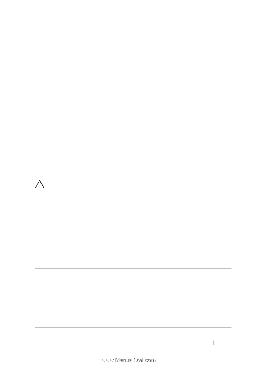
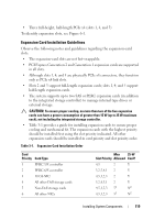
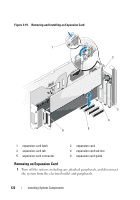
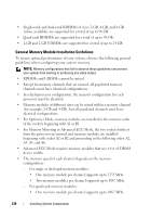
• Three full-height, half-length PCIe x4 (slots 1, 4, and 5) To identify expansion slots, see Figure 6-1. Expansion Card Installation Guidelines Observe the following notes and guidelines regarding the expansion-card slots: • The expansion-card slots are not hot-swappable. • PCI Express Generation 2 and Generation 1 expansion cards are supported in all slots. • Although slots 1, 4, and 5 are physically PCIe x8 connectors, they function only as PCIe x4 link slots. • Slots 2 and 3 support full-length expansion cards; slots 1, 4, and 5 support half-length expansion cards. • The system supports up to two SAS or PERC expansion cards (in addition to the integrated storage controller) to manage internal tape drives or external storage. CAUTION: To ensure proper cooling, no more than two of the five expansion cards can have a power consumption of greater than 15 W (up to 25 W maximum each), not including the integrated storage controller. • Table 3-1 provides a guide for installing expansion cards to ensure proper cooling and mechanical fit. The expansion cards with the highest priority should be installed first using the slot priority indicated. All other expansion cards should be installed in card priority and slot priority order. Table 3-1. Expansion-Card Installation Order Card Priority Card Type 1 PERC 5/E controller 2 PERC 6/E controller 3 10 Gb NIC 4 All other Dell storage cards 5 Non-Dell storage cards 6 All other NICs Max 25-W Slot Priority Allowed Card? 4,5 2 Y 3,2,5,4,1 2 Y 4,5,1,2,3 2 Y 3,2,4,5,1 2 Y 4,5,1,2,3 51 N2 4,5,1,2,3 51 N2 Installing System Components 119
-
 1
1 -
2
-
3
-
4
-
5
-
6
-
7
-
8
-
9
-
10
-
11
-
12
-
13
-
14
-
15
-
16
-
17
-
18
-
19
-
20
-
21
-
22
-
23
-
24
-
25
-
26
-
27
-
28
-
29
-
30
-
31
-
32
-
33
-
34
-
35
-
36
-
37
-
38
-
39
-
40
-
41
-
42
-
43
-
44
-
45
-
46
-
47
-
48
-
49
-
50
-
51
-
52
-
53
-
54
-
55
-
56
-
57
-
58
-
59
-
60
-
61
-
62
-
63
-
64
-
65
-
66
-
67
-
68
-
69
-
70
-
71
-
72
-
73
-
74
-
75
-
76
-
77
-
78
-
79
-
80
-
81
-
82
-
83
-
84
-
85
-
86
-
87
-
88
-
89
-
90
-
91
-
92
-
93
-
94
-
95
-
96
-
97
-
98
-
99
-
100
-
101
-
102
-
103
-
104
-
105
-
106
-
107
-
108
-
109
-
110
-
111
-
112
-
113
-
 114
114 -
 115
115 -
 116
116 -
 117
117 -
 118
118 -
 119
119 -
 120
120 -
 121
121 -
 122
122 -
 123
123 -
 124
124 -
125
-
126
-
127
-
128
-
129
-
130
-
131
-
132
-
133
-
134
-
135
-
136
-
137
-
138
-
139
-
140
-
141
-
142
-
143
-
144
-
145
-
146
-
147
-
148
-
149
-
150
-
151
-
152
-
153
-
154
-
155
-
156
-
157
-
158
-
159
-
160
-
161
-
162
-
163
-
164
-
165
-
166
-
167
-
168
-
169
-
170
-
171
-
172
-
173
-
174
-
175
-
176
-
177
-
178
-
179
-
180
-
181
-
182
-
183
-
184
-
185
-
186
-
187
-
188
-
189
-
190
-
191
-
192
-
193
-
194
-
195
-
196
-
197
-
198
-
199
-
200
-
201
-
202
-
203
-
204
-
205
-
206
 |
 |