Dell PowerEdge T610 Hardware Owner's Manual - Page 82
Hard Drives - parts
 |
View all Dell PowerEdge T610 manuals
Add to My Manuals
Save this manual to your list of manuals |
Page 82 highlights
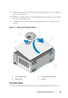
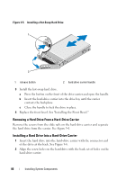
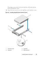
2 Ensure that no tools or extra parts are left inside the system. 3 Reinstall the system cover: a Place the bottom edge of the cover, opposite from the cover release latch, into the slots in the system chassis. b Lower the cover into the chassis. c Press the latch end of the cover into the chassis until the latch locks into place. d Turn the cover latch release lock clockwise to the locked position. 4 Place the system upright and on its feet on a flat, stable surface. 5 Rotate the system feet outward. 6 Replace the front bezel. See "Installing the Front Bezel." 7 Reattach any peripherals, then connect the system to the electrical outlet. 8 Turn on the system and attached peripherals. Hard Drives Depending on your chassis and backplane, your system has one of the following configurations: • Eight 2.5-inch drive bays • Eight 3.5-inch drive bays All chassis support hot-swappable SAS and SATA hard drives, and the 2.5inch-bay chassis also supports hot-swappable SSD hard drives in systems with integrated PERC controllers. All drives are installed at the front of the system and connect to the system board through the SAS backplane. Hard drives are supplied in special hotswappable hard-drive carriers that fit in the hard-drive bays. CAUTION: Before attempting to remove or install a drive while the system is running, see the documentation for the storage controller card to ensure that the host adapter is configured correctly to support hot-swap drive removal and insertion. CAUTION: Do not turn off or reboot your system while the drive is being formatted. Doing so can cause a drive failure. 82 Installing System Components
-
 1
1 -
2
-
3
-
4
-
5
-
6
-
7
-
8
-
9
-
10
-
11
-
12
-
13
-
14
-
15
-
16
-
17
-
18
-
19
-
20
-
21
-
22
-
23
-
24
-
25
-
26
-
27
-
28
-
29
-
30
-
31
-
32
-
33
-
34
-
35
-
36
-
37
-
38
-
39
-
40
-
41
-
42
-
43
-
44
-
45
-
46
-
47
-
48
-
49
-
50
-
51
-
52
-
53
-
54
-
55
-
56
-
57
-
58
-
59
-
60
-
61
-
62
-
63
-
64
-
65
-
66
-
67
-
68
-
69
-
70
-
71
-
72
-
73
-
74
-
75
-
76
-
 77
77 -
 78
78 -
 79
79 -
 80
80 -
 81
81 -
 82
82 -
 83
83 -
 84
84 -
 85
85 -
 86
86 -
 87
87 -
88
-
89
-
90
-
91
-
92
-
93
-
94
-
95
-
96
-
97
-
98
-
99
-
100
-
101
-
102
-
103
-
104
-
105
-
106
-
107
-
108
-
109
-
110
-
111
-
112
-
113
-
114
-
115
-
116
-
117
-
118
-
119
-
120
-
121
-
122
-
123
-
124
-
125
-
126
-
127
-
128
-
129
-
130
-
131
-
132
-
133
-
134
-
135
-
136
-
137
-
138
-
139
-
140
-
141
-
142
-
143
-
144
-
145
-
146
-
147
-
148
-
149
-
150
-
151
-
152
-
153
-
154
-
155
-
156
-
157
-
158
-
159
-
160
-
161
-
162
-
163
-
164
-
165
-
166
-
167
-
168
-
169
-
170
-
171
-
172
-
173
-
174
-
175
-
176
-
177
-
178
-
179
-
180
-
181
-
182
-
183
-
184
-
185
-
186
-
187
-
188
-
189
-
190
-
191
-
192
-
193
-
194
-
195
-
196
-
197
-
198
-
199
-
200
-
201
-
202
-
203
-
204
-
205
-
206
 |
 |