Dell PowerEdge T610 Hardware Owner's Manual - Page 90
Expansion Card Stabilizer, Removing a Power Supply Blank, Removing the Expansion Card Stabilizer
 |
View all Dell PowerEdge T610 manuals
Add to My Manuals
Save this manual to your list of manuals |
Page 90 highlights
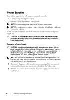
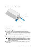
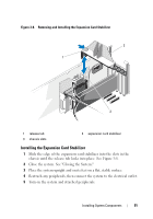
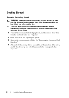
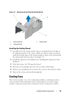
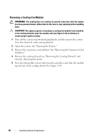
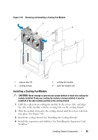
CAUTION: When connecting the power cable, secure the cable with the Velcro strap. NOTE: When hot-adding or hot-swapping a new power supply, allow several seconds for the system to recognize the power supply and determine whether it is working properly. The power supply status indicator will turn green to signify that the power supply is functioning properly (see Figure 1-5). Removing a Power Supply Blank If you are installing a second power supply, remove the power supply blank in the bay by pulling firmly on the hole in the middle of the blank. CAUTION: To ensure proper system cooling, the power supply blank must be installed in the second power supply bay in a non-redundant configuration. Remove the power supply blank only if you are installing a second power supply. Installing a Power Supply Blank NOTE: Install the power supply blank only in the second power supply bay. To install the power supply blank, align the blank with the power supply bay and insert it into the chassis until it clicks into place. Expansion Card Stabilizer Removing the Expansion Card Stabilizer 1 Turn off the system and attached peripherals, and disconnect the system from the electrical outlet and peripherals. 2 Open the system. See "Opening the System." 3 Press the release tab and lift the expansion card stabilizer out of slots in the chassis. See Figure 3-8. 90 Installing System Components
-
 1
1 -
2
-
3
-
4
-
5
-
6
-
7
-
8
-
9
-
10
-
11
-
12
-
13
-
14
-
15
-
16
-
17
-
18
-
19
-
20
-
21
-
22
-
23
-
24
-
25
-
26
-
27
-
28
-
29
-
30
-
31
-
32
-
33
-
34
-
35
-
36
-
37
-
38
-
39
-
40
-
41
-
42
-
43
-
44
-
45
-
46
-
47
-
48
-
49
-
50
-
51
-
52
-
53
-
54
-
55
-
56
-
57
-
58
-
59
-
60
-
61
-
62
-
63
-
64
-
65
-
66
-
67
-
68
-
69
-
70
-
71
-
72
-
73
-
74
-
75
-
76
-
77
-
78
-
79
-
80
-
81
-
82
-
83
-
84
-
 85
85 -
 86
86 -
 87
87 -
 88
88 -
 89
89 -
 90
90 -
 91
91 -
 92
92 -
 93
93 -
 94
94 -
 95
95 -
96
-
97
-
98
-
99
-
100
-
101
-
102
-
103
-
104
-
105
-
106
-
107
-
108
-
109
-
110
-
111
-
112
-
113
-
114
-
115
-
116
-
117
-
118
-
119
-
120
-
121
-
122
-
123
-
124
-
125
-
126
-
127
-
128
-
129
-
130
-
131
-
132
-
133
-
134
-
135
-
136
-
137
-
138
-
139
-
140
-
141
-
142
-
143
-
144
-
145
-
146
-
147
-
148
-
149
-
150
-
151
-
152
-
153
-
154
-
155
-
156
-
157
-
158
-
159
-
160
-
161
-
162
-
163
-
164
-
165
-
166
-
167
-
168
-
169
-
170
-
171
-
172
-
173
-
174
-
175
-
176
-
177
-
178
-
179
-
180
-
181
-
182
-
183
-
184
-
185
-
186
-
187
-
188
-
189
-
190
-
191
-
192
-
193
-
194
-
195
-
196
-
197
-
198
-
199
-
200
-
201
-
202
-
203
-
204
-
205
-
206
 |
 |