Dell PowerEdge T610 Hardware Owner's Manual - Page 139
Integrated Storage Controller Card., towards the back of the system. See
 |
View all Dell PowerEdge T610 manuals
Add to My Manuals
Save this manual to your list of manuals |
Page 139 highlights
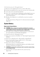
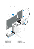
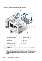
3 Remove the expansion card stabilizer. See "Removing the Expansion Card Stabilizer." 4 Remove the cooling shroud. See "Removing the Cooling Shroud." 5 Remove the integrated storage controller card. See "Removing an Integrated Storage Controller Card." 6 Remove the expansion card stabilizer bracket: Pull the blue release lever, and slide the expansion card stabilizer bracket up and out of the chassis. See Figure 3-27. CAUTION: Do not pull on the control panel cable to unseat the connector. Doing so can damage the cable. 7 Disconnect the control panel cable from the system board (see Figure 3-24): a Squeeze the metal tabs on the ends of the cable connector. b Gently work the connector out of the socket. 8 Remove the outer cover from the top side of the chassis to access the remaining control panel screw. a Using a #2 Phillips screwdriver, remove the two hex-head Phillips screws securing the outer cover from the back of the system. b Pressing firmly on the front edge of the cover, slide the cover slightly towards the back of the system. See Figure 3-24. c Remove the cover by first pulling away the top edge, then pulling away the bottom edge, removing the metal hooks from the securing slots in the chassis. See Figure 3-24. 9 Using a T10 Torx driver, remove the control panel screws that secure the control panel to the chassis. See Figure 3-24. 10 Slide the control panel assembly with the control panel cable out of the the chassis. See Figure 3-24. 11 Remove the control panel cable from the control panel board. See Figure 3-24. Installing System Components 139
-
 1
1 -
2
-
3
-
4
-
5
-
6
-
7
-
8
-
9
-
10
-
11
-
12
-
13
-
14
-
15
-
16
-
17
-
18
-
19
-
20
-
21
-
22
-
23
-
24
-
25
-
26
-
27
-
28
-
29
-
30
-
31
-
32
-
33
-
34
-
35
-
36
-
37
-
38
-
39
-
40
-
41
-
42
-
43
-
44
-
45
-
46
-
47
-
48
-
49
-
50
-
51
-
52
-
53
-
54
-
55
-
56
-
57
-
58
-
59
-
60
-
61
-
62
-
63
-
64
-
65
-
66
-
67
-
68
-
69
-
70
-
71
-
72
-
73
-
74
-
75
-
76
-
77
-
78
-
79
-
80
-
81
-
82
-
83
-
84
-
85
-
86
-
87
-
88
-
89
-
90
-
91
-
92
-
93
-
94
-
95
-
96
-
97
-
98
-
99
-
100
-
101
-
102
-
103
-
104
-
105
-
106
-
107
-
108
-
109
-
110
-
111
-
112
-
113
-
114
-
115
-
116
-
117
-
118
-
119
-
120
-
121
-
122
-
123
-
124
-
125
-
126
-
127
-
128
-
129
-
130
-
131
-
132
-
133
-
 134
134 -
 135
135 -
 136
136 -
 137
137 -
 138
138 -
 139
139 -
 140
140 -
 141
141 -
 142
142 -
 143
143 -
 144
144 -
145
-
146
-
147
-
148
-
149
-
150
-
151
-
152
-
153
-
154
-
155
-
156
-
157
-
158
-
159
-
160
-
161
-
162
-
163
-
164
-
165
-
166
-
167
-
168
-
169
-
170
-
171
-
172
-
173
-
174
-
175
-
176
-
177
-
178
-
179
-
180
-
181
-
182
-
183
-
184
-
185
-
186
-
187
-
188
-
189
-
190
-
191
-
192
-
193
-
194
-
195
-
196
-
197
-
198
-
199
-
200
-
201
-
202
-
203
-
204
-
205
-
206
 |
 |