Dell PowerEdge T610 Hardware Owner's Manual - Page 108
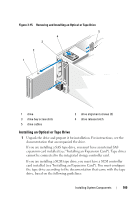
Replace the cooling shroud. See Installing the Cooling Shroud., Tape Drive.
 |
View all Dell PowerEdge T610 manuals
Add to My Manuals
Save this manual to your list of manuals |
Page 108 highlights
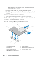
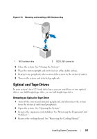
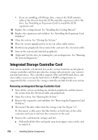
5 Disconnect the power and data cables from the back of the drive. See Figure 3-15. 6 Slide the drive release latch in the direction of the arrow to release the shoulder screws. See Figure 3-15. 7 Slide the drive out to remove it from the drive bay. 8 If you are installing another drive in the bay, see "Installing an Optical or Tape Drive." If the drive is being permanently removed, install a drive blank in the empty drive bay. Slide the drive blank into the drive bay until the drive release latch locks into place. See Figure 3-15. 9 Replace the cooling shroud. See "Installing the Cooling Shroud." 10 Replace the expansion card stabilizer. See "Installing the Expansion Card Stabilizer." 11 Close the system. See "Closing the System." 12 Place the system upright and on its feet on a flat, stable surface. 13 Reattach any peripherals, then connect the system to the electrical outlet. 14 Turn on the system and attached peripherals. 108 Installing System Components
-
 1
1 -
2
-
3
-
4
-
5
-
6
-
7
-
8
-
9
-
10
-
11
-
12
-
13
-
14
-
15
-
16
-
17
-
18
-
19
-
20
-
21
-
22
-
23
-
24
-
25
-
26
-
27
-
28
-
29
-
30
-
31
-
32
-
33
-
34
-
35
-
36
-
37
-
38
-
39
-
40
-
41
-
42
-
43
-
44
-
45
-
46
-
47
-
48
-
49
-
50
-
51
-
52
-
53
-
54
-
55
-
56
-
57
-
58
-
59
-
60
-
61
-
62
-
63
-
64
-
65
-
66
-
67
-
68
-
69
-
70
-
71
-
72
-
73
-
74
-
75
-
76
-
77
-
78
-
79
-
80
-
81
-
82
-
83
-
84
-
85
-
86
-
87
-
88
-
89
-
90
-
91
-
92
-
93
-
94
-
95
-
96
-
97
-
98
-
99
-
100
-
101
-
102
-
 103
103 -
 104
104 -
 105
105 -
 106
106 -
 107
107 -
 108
108 -
 109
109 -
 110
110 -
 111
111 -
 112
112 -
 113
113 -
114
-
115
-
116
-
117
-
118
-
119
-
120
-
121
-
122
-
123
-
124
-
125
-
126
-
127
-
128
-
129
-
130
-
131
-
132
-
133
-
134
-
135
-
136
-
137
-
138
-
139
-
140
-
141
-
142
-
143
-
144
-
145
-
146
-
147
-
148
-
149
-
150
-
151
-
152
-
153
-
154
-
155
-
156
-
157
-
158
-
159
-
160
-
161
-
162
-
163
-
164
-
165
-
166
-
167
-
168
-
169
-
170
-
171
-
172
-
173
-
174
-
175
-
176
-
177
-
178
-
179
-
180
-
181
-
182
-
183
-
184
-
185
-
186
-
187
-
188
-
189
-
190
-
191
-
192
-
193
-
194
-
195
-
196
-
197
-
198
-
199
-
200
-
201
-
202
-
203
-
204
-
205
-
206
 |
 |