Dell PowerEdge T610 Hardware Owner's Manual - Page 93
Cooling Fans, Installing the Cooling Shroud
 |
View all Dell PowerEdge T610 manuals
Add to My Manuals
Save this manual to your list of manuals |
Page 93 highlights
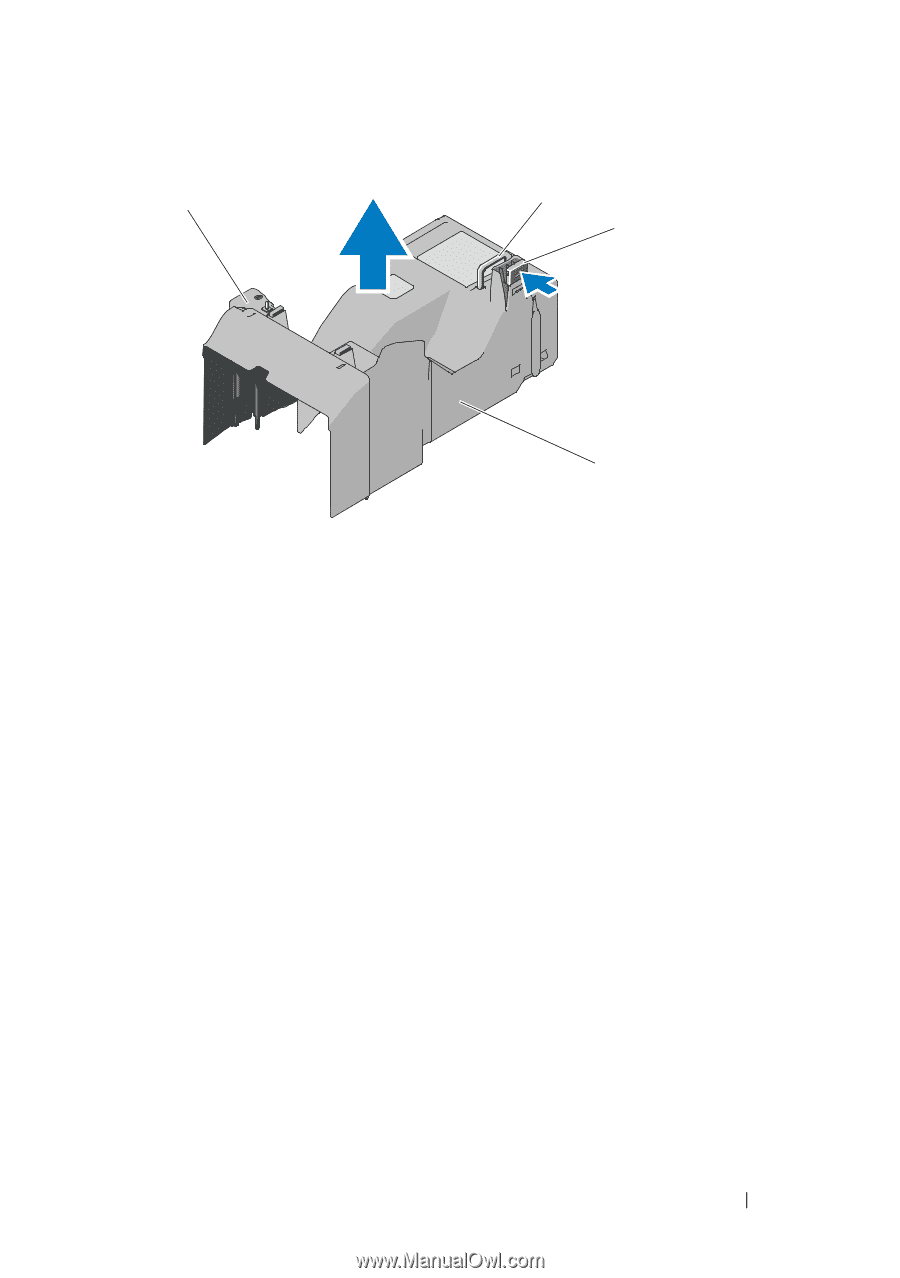
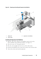
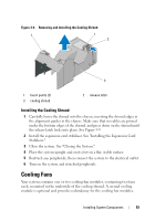
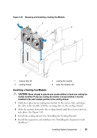
Figure 3-9. Removing and Installing the Cooling Shroud 1 1 2 3 1 touch points (2) 3 cooling shroud 2 release latch Installing the Cooling Shroud 1 Carefully lower the shroud into the chassis, inserting the shroud edges in the alignment guides in the chassis. Make sure that no cables are pinned under the bottom edges of the shroud, and press down on the shroud until the release latch locks into place. See Figure 3-9. 2 Install the expansion card stabilizer. See "Installing the Expansion Card Stabilizer." 3 Close the system. See "Closing the System." 4 Place the system upright and on its feet on a flat, stable surface. 5 Reattach any peripherals, then connect the system to the electrical outlet. 6 Turn on the system and attached peripherals. Cooling Fans Your system contains one or two cooling-fan modules, containing two fans each, mounted in the underside of the cooling shroud. A second cooling module is optional and provides redundancy for the cooling-fan modules. Installing System Components 93
-
 1
1 -
2
-
3
-
4
-
5
-
6
-
7
-
8
-
9
-
10
-
11
-
12
-
13
-
14
-
15
-
16
-
17
-
18
-
19
-
20
-
21
-
22
-
23
-
24
-
25
-
26
-
27
-
28
-
29
-
30
-
31
-
32
-
33
-
34
-
35
-
36
-
37
-
38
-
39
-
40
-
41
-
42
-
43
-
44
-
45
-
46
-
47
-
48
-
49
-
50
-
51
-
52
-
53
-
54
-
55
-
56
-
57
-
58
-
59
-
60
-
61
-
62
-
63
-
64
-
65
-
66
-
67
-
68
-
69
-
70
-
71
-
72
-
73
-
74
-
75
-
76
-
77
-
78
-
79
-
80
-
81
-
82
-
83
-
84
-
85
-
86
-
87
-
 88
88 -
 89
89 -
 90
90 -
 91
91 -
 92
92 -
 93
93 -
 94
94 -
 95
95 -
 96
96 -
 97
97 -
 98
98 -
99
-
100
-
101
-
102
-
103
-
104
-
105
-
106
-
107
-
108
-
109
-
110
-
111
-
112
-
113
-
114
-
115
-
116
-
117
-
118
-
119
-
120
-
121
-
122
-
123
-
124
-
125
-
126
-
127
-
128
-
129
-
130
-
131
-
132
-
133
-
134
-
135
-
136
-
137
-
138
-
139
-
140
-
141
-
142
-
143
-
144
-
145
-
146
-
147
-
148
-
149
-
150
-
151
-
152
-
153
-
154
-
155
-
156
-
157
-
158
-
159
-
160
-
161
-
162
-
163
-
164
-
165
-
166
-
167
-
168
-
169
-
170
-
171
-
172
-
173
-
174
-
175
-
176
-
177
-
178
-
179
-
180
-
181
-
182
-
183
-
184
-
185
-
186
-
187
-
188
-
189
-
190
-
191
-
192
-
193
-
194
-
195
-
196
-
197
-
198
-
199
-
200
-
201
-
202
-
203
-
204
-
205
-
206
 |
 |