Dell PowerEdge T610 Hardware Owner's Manual - Page 115
Removing the Expansion Card Stabilizer Bracket, Place the system upright and on its feet on a flat - drivers
 |
View all Dell PowerEdge T610 manuals
Add to My Manuals
Save this manual to your list of manuals |
Page 115 highlights
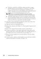
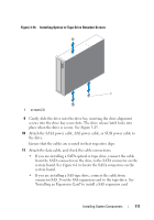
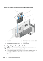
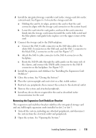
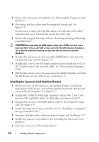
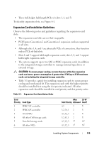
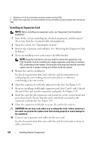
2 Install the integrated storage controller card in the storage-card slot on the system board. See Figure 6-1 to locate the storage-card slot. a Holding the card by its edges, position the card so that the card connector aligns with the storage-card connector on the system board. b Lower the card into the card guides, and insert the card connector firmly into the storage-card connector until the card is fully seated and the blue plastic card guide locks in place over the upper corner of the card. 3 Connect the storage card to the SAS backplane: a Connect the SAS_0 cable connector on the SAS data cable to the white SAS_0 connector on the SAS card, and the SAS_1 connector to the black SAS_1 connector on the card. See Figure 3-17. b Attach the SAS A cable connector to the SAS A connector on the backplane. c Route the SAS B cable through the cable guides on the inner side of the chassis, and connect the SAS B cable connector to the SAS B connector on the backplane. See Figure 3-25. 4 Install the expansion card stabilizer. See "Installing the Expansion Card Stabilizer." 5 Close the system. See "Closing the System." 6 Place the system upright and on its feet on a flat, stable surface. 7 Reattach any peripherals, then connect the system to the electrical outlet. 8 Turn on the system and attached peripherals. 9 Install any device drivers required for the card as described in the documentation for the card. Removing the Expansion Card Stabilizer Bracket The expansion card stabilizer bracket stabilizes the integrated storage card and any full-length expansion cards installed in slot 2 or slot 3. 1 Turn off the system, including any attached peripherals, and disconnect the system from the electrical outlet and peripherals. 2 Open the system. See "Opening the System." Installing System Components 115
-
 1
1 -
2
-
3
-
4
-
5
-
6
-
7
-
8
-
9
-
10
-
11
-
12
-
13
-
14
-
15
-
16
-
17
-
18
-
19
-
20
-
21
-
22
-
23
-
24
-
25
-
26
-
27
-
28
-
29
-
30
-
31
-
32
-
33
-
34
-
35
-
36
-
37
-
38
-
39
-
40
-
41
-
42
-
43
-
44
-
45
-
46
-
47
-
48
-
49
-
50
-
51
-
52
-
53
-
54
-
55
-
56
-
57
-
58
-
59
-
60
-
61
-
62
-
63
-
64
-
65
-
66
-
67
-
68
-
69
-
70
-
71
-
72
-
73
-
74
-
75
-
76
-
77
-
78
-
79
-
80
-
81
-
82
-
83
-
84
-
85
-
86
-
87
-
88
-
89
-
90
-
91
-
92
-
93
-
94
-
95
-
96
-
97
-
98
-
99
-
100
-
101
-
102
-
103
-
104
-
105
-
106
-
107
-
108
-
109
-
 110
110 -
 111
111 -
 112
112 -
 113
113 -
 114
114 -
 115
115 -
 116
116 -
 117
117 -
 118
118 -
 119
119 -
 120
120 -
121
-
122
-
123
-
124
-
125
-
126
-
127
-
128
-
129
-
130
-
131
-
132
-
133
-
134
-
135
-
136
-
137
-
138
-
139
-
140
-
141
-
142
-
143
-
144
-
145
-
146
-
147
-
148
-
149
-
150
-
151
-
152
-
153
-
154
-
155
-
156
-
157
-
158
-
159
-
160
-
161
-
162
-
163
-
164
-
165
-
166
-
167
-
168
-
169
-
170
-
171
-
172
-
173
-
174
-
175
-
176
-
177
-
178
-
179
-
180
-
181
-
182
-
183
-
184
-
185
-
186
-
187
-
188
-
189
-
190
-
191
-
192
-
193
-
194
-
195
-
196
-
197
-
198
-
199
-
200
-
201
-
202
-
203
-
204
-
205
-
206
 |
 |