Dell PowerEdge T610 Hardware Owner's Manual - Page 141
Installing the Control Panel Assembly
 |
View all Dell PowerEdge T610 manuals
Add to My Manuals
Save this manual to your list of manuals |
Page 141 highlights
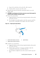
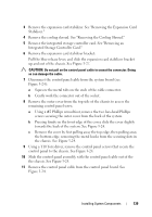
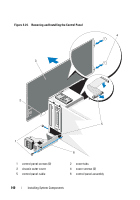
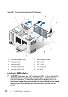
Installing the Control Panel Assembly CAUTION: Many repairs may only be done by a certified service technician. You should only perform troubleshooting and simple repairs as authorized in your product documentation, or as directed by the online or telephone service and support team. Damage due to servicing that is not authorized by Dell is not covered by your warranty. Read and follow the safety instructions that came with the product. 1 Connect the control panel cable to the control panel board. See Figure 3-24. 2 Insert the control panel assembly, cable first, into the chassis. See Figure 3-24. Gently work the control panel assembly into the chassis until it is fully seated against the front of the chassis. 3 Replace the Torx screw on the top side of the chassis. See Figure 3-24. 4 Install the outer cover on the top side of the chassis. a Insert the cover tabs into the slots in the top side of the chassis. See Figure 3-24. b Hook the top edge of the cover over the top edge of the chassis. See Figure 3-24. c Slide the cover towards the front of the system. See Figure 3-24. d Replace the two hex-head Phillips screws on the back of the system to secure the cover to the chassis. 5 Replace the Torx screw on the front of the system to secure the control panel assembly to the chassis. See Figure 3-24. 6 Connect the control panel cable to CTRL_PNL connector on the system board. See Figure 6-1 for the connector location. 7 Install the expansion-card stabilizer bracket: Fit the slots on the bracket over the metal guides in the chassis, and slide the bracket downwards until the release latch locks into place. See Figure 3-27. 8 Install the cooling shroud. See "Installing the Cooling Shroud." 9 Install the expansion card stabilizer. See "Installing the Expansion Card Stabilizer." Installing System Components 141
-
 1
1 -
2
-
3
-
4
-
5
-
6
-
7
-
8
-
9
-
10
-
11
-
12
-
13
-
14
-
15
-
16
-
17
-
18
-
19
-
20
-
21
-
22
-
23
-
24
-
25
-
26
-
27
-
28
-
29
-
30
-
31
-
32
-
33
-
34
-
35
-
36
-
37
-
38
-
39
-
40
-
41
-
42
-
43
-
44
-
45
-
46
-
47
-
48
-
49
-
50
-
51
-
52
-
53
-
54
-
55
-
56
-
57
-
58
-
59
-
60
-
61
-
62
-
63
-
64
-
65
-
66
-
67
-
68
-
69
-
70
-
71
-
72
-
73
-
74
-
75
-
76
-
77
-
78
-
79
-
80
-
81
-
82
-
83
-
84
-
85
-
86
-
87
-
88
-
89
-
90
-
91
-
92
-
93
-
94
-
95
-
96
-
97
-
98
-
99
-
100
-
101
-
102
-
103
-
104
-
105
-
106
-
107
-
108
-
109
-
110
-
111
-
112
-
113
-
114
-
115
-
116
-
117
-
118
-
119
-
120
-
121
-
122
-
123
-
124
-
125
-
126
-
127
-
128
-
129
-
130
-
131
-
132
-
133
-
134
-
135
-
 136
136 -
 137
137 -
 138
138 -
 139
139 -
 140
140 -
 141
141 -
 142
142 -
 143
143 -
 144
144 -
 145
145 -
 146
146 -
147
-
148
-
149
-
150
-
151
-
152
-
153
-
154
-
155
-
156
-
157
-
158
-
159
-
160
-
161
-
162
-
163
-
164
-
165
-
166
-
167
-
168
-
169
-
170
-
171
-
172
-
173
-
174
-
175
-
176
-
177
-
178
-
179
-
180
-
181
-
182
-
183
-
184
-
185
-
186
-
187
-
188
-
189
-
190
-
191
-
192
-
193
-
194
-
195
-
196
-
197
-
198
-
199
-
200
-
201
-
202
-
203
-
204
-
205
-
206
 |
 |