Dell PowerEdge T610 Hardware Owner's Manual - Page 135
and set the processor lightly, rocessor
 |
View all Dell PowerEdge T610 manuals
Add to My Manuals
Save this manual to your list of manuals |
Page 135 highlights
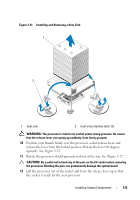
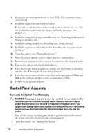
NOTE: In a single-processor configuration, the CPU1 socket must be used. 1 If you are adding a second processor for the first time, remove the heatsink blank and the processor blank from the vacant processor socket. Removing the blanks is similar to removing a processor. See "Removing a Processor." 2 Unpack the new processor. If the processor has previously been used in a system, remove any remaining thermal grease from the processor using a lint-free cloth. 3 Align the processor with the socket keys on the ZIF socket. See Figure 3-22. 4 Install the processor in the socket. CAUTION: Positioning the processor incorrectly can permanently damage the system board or the processor. Be careful not to bend the pins in the socket. a With the release lever on the processor socket in the open position, align the processor with the socket keys and set the processor lightly in the socket. CAUTION: Do not use force to seat the processor. When the processor is positioned correctly, it engages easily into the socket. b Close the processor shield. c Rotate the socket release lever down until it snaps into place. 5 Install the heat sink. a Using a clean lint-free cloth, remove the thermal grease from the heat sink. CAUTION: Applying too much thermal grease can result in excess grease coming in contact with and contaminating the processor socket. b Open the grease packet included with your processor kit and apply a small amount of thermal grease (the size of a fingernail) to the center of the top of the new processor. c Place the heat sink on the processor. See Figure 3-21. d Close the two heat-sink retention latches. See Figure 3-21. 6 Install the cooling shroud. See "Installing the Cooling Shroud." 7 Install the expansion card stabilizer. See "Installing the Expansion Card Stabilizer." Installing System Components 135
-
 1
1 -
2
-
3
-
4
-
5
-
6
-
7
-
8
-
9
-
10
-
11
-
12
-
13
-
14
-
15
-
16
-
17
-
18
-
19
-
20
-
21
-
22
-
23
-
24
-
25
-
26
-
27
-
28
-
29
-
30
-
31
-
32
-
33
-
34
-
35
-
36
-
37
-
38
-
39
-
40
-
41
-
42
-
43
-
44
-
45
-
46
-
47
-
48
-
49
-
50
-
51
-
52
-
53
-
54
-
55
-
56
-
57
-
58
-
59
-
60
-
61
-
62
-
63
-
64
-
65
-
66
-
67
-
68
-
69
-
70
-
71
-
72
-
73
-
74
-
75
-
76
-
77
-
78
-
79
-
80
-
81
-
82
-
83
-
84
-
85
-
86
-
87
-
88
-
89
-
90
-
91
-
92
-
93
-
94
-
95
-
96
-
97
-
98
-
99
-
100
-
101
-
102
-
103
-
104
-
105
-
106
-
107
-
108
-
109
-
110
-
111
-
112
-
113
-
114
-
115
-
116
-
117
-
118
-
119
-
120
-
121
-
122
-
123
-
124
-
125
-
126
-
127
-
128
-
129
-
 130
130 -
 131
131 -
 132
132 -
 133
133 -
 134
134 -
 135
135 -
 136
136 -
 137
137 -
 138
138 -
 139
139 -
 140
140 -
141
-
142
-
143
-
144
-
145
-
146
-
147
-
148
-
149
-
150
-
151
-
152
-
153
-
154
-
155
-
156
-
157
-
158
-
159
-
160
-
161
-
162
-
163
-
164
-
165
-
166
-
167
-
168
-
169
-
170
-
171
-
172
-
173
-
174
-
175
-
176
-
177
-
178
-
179
-
180
-
181
-
182
-
183
-
184
-
185
-
186
-
187
-
188
-
189
-
190
-
191
-
192
-
193
-
194
-
195
-
196
-
197
-
198
-
199
-
200
-
201
-
202
-
203
-
204
-
205
-
206
 |
 |