Dell PowerEdge T610 Hardware Owner's Manual - Page 111
system board. See to locate the SATA connectors on
 |
View all Dell PowerEdge T610 manuals
Add to My Manuals
Save this manual to your list of manuals |
Page 111 highlights
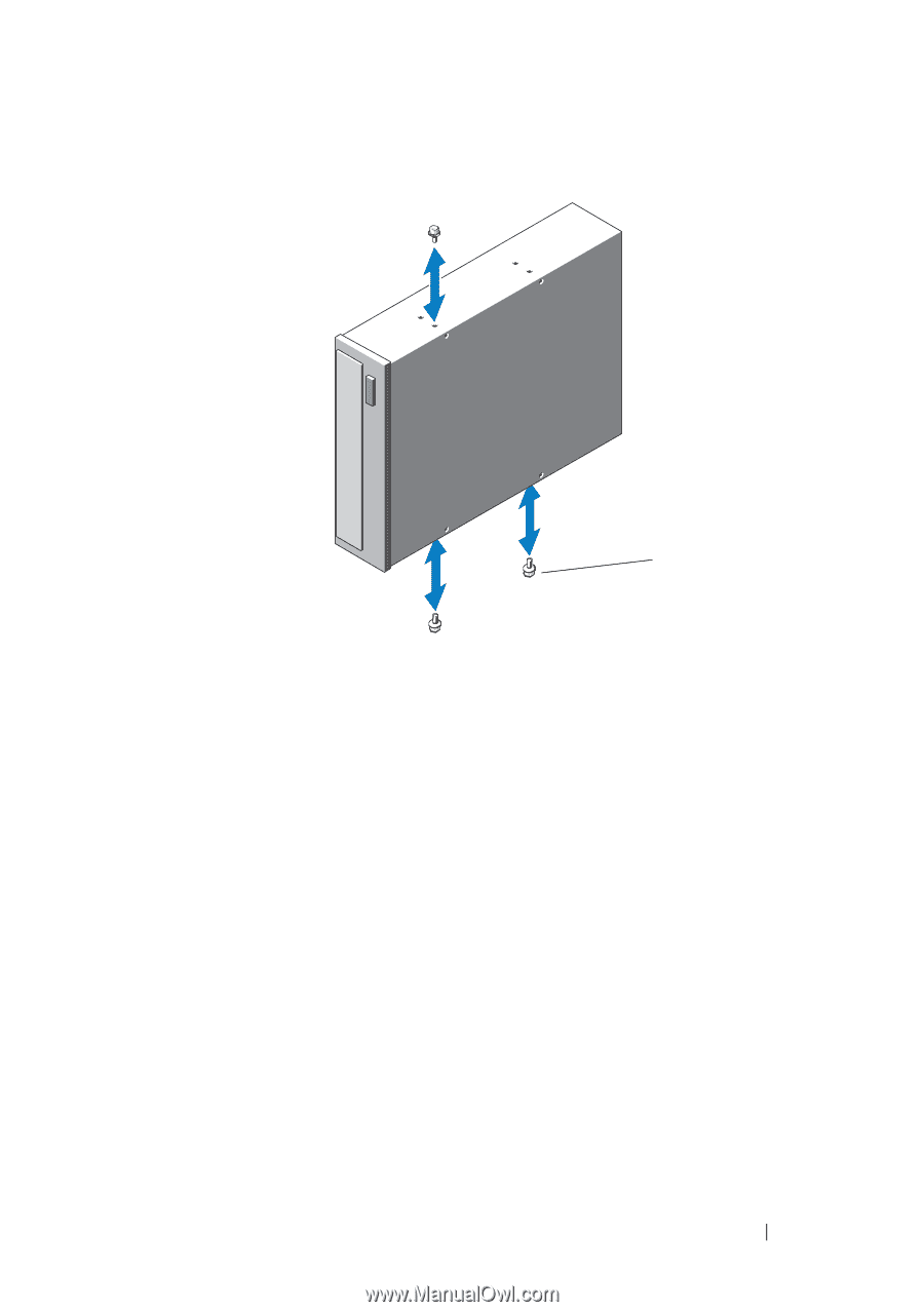
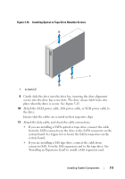
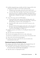
Figure 3-16. Installing Optical or Tape Drive Shoulder Screws 1 1 screws (3) 9 Gently slide the drive into the drive bay, inserting the drive alignment screws into the drive bay screw slots. The drive release latch locks into place when the drive is secure. See Figure 3-15. 10 Attach the SATA power cable, SAS power cable, or SCSI power cable to the drive. Ensure that the cables are secured in their respective clips. 11 Attach the data cable, and check the cable connections: • If you are installing a SATA optical or tape drive, connect the cable from the SATA connector on the drive to the SATA connector on the system board. See Figure 6-1 to locate the SATA connectors on the system board. • If you are installing a SAS tape drive, connect the cable from connector SAS_0 on the SAS expansion card to the tape drive. See "Installing an Expansion Card" to install a SAS expansion card. Installing System Components 111
-
 1
1 -
2
-
3
-
4
-
5
-
6
-
7
-
8
-
9
-
10
-
11
-
12
-
13
-
14
-
15
-
16
-
17
-
18
-
19
-
20
-
21
-
22
-
23
-
24
-
25
-
26
-
27
-
28
-
29
-
30
-
31
-
32
-
33
-
34
-
35
-
36
-
37
-
38
-
39
-
40
-
41
-
42
-
43
-
44
-
45
-
46
-
47
-
48
-
49
-
50
-
51
-
52
-
53
-
54
-
55
-
56
-
57
-
58
-
59
-
60
-
61
-
62
-
63
-
64
-
65
-
66
-
67
-
68
-
69
-
70
-
71
-
72
-
73
-
74
-
75
-
76
-
77
-
78
-
79
-
80
-
81
-
82
-
83
-
84
-
85
-
86
-
87
-
88
-
89
-
90
-
91
-
92
-
93
-
94
-
95
-
96
-
97
-
98
-
99
-
100
-
101
-
102
-
103
-
104
-
105
-
 106
106 -
 107
107 -
 108
108 -
 109
109 -
 110
110 -
 111
111 -
 112
112 -
 113
113 -
 114
114 -
 115
115 -
 116
116 -
117
-
118
-
119
-
120
-
121
-
122
-
123
-
124
-
125
-
126
-
127
-
128
-
129
-
130
-
131
-
132
-
133
-
134
-
135
-
136
-
137
-
138
-
139
-
140
-
141
-
142
-
143
-
144
-
145
-
146
-
147
-
148
-
149
-
150
-
151
-
152
-
153
-
154
-
155
-
156
-
157
-
158
-
159
-
160
-
161
-
162
-
163
-
164
-
165
-
166
-
167
-
168
-
169
-
170
-
171
-
172
-
173
-
174
-
175
-
176
-
177
-
178
-
179
-
180
-
181
-
182
-
183
-
184
-
185
-
186
-
187
-
188
-
189
-
190
-
191
-
192
-
193
-
194
-
195
-
196
-
197
-
198
-
199
-
200
-
201
-
202
-
203
-
204
-
205
-
206
 |
 |