Dell PowerEdge T610 Hardware Owner's Manual - Page 128
Installing Memory Modules, WARNING, CAUTION
 |
View all Dell PowerEdge T610 manuals
Add to My Manuals
Save this manual to your list of manuals |
Page 128 highlights
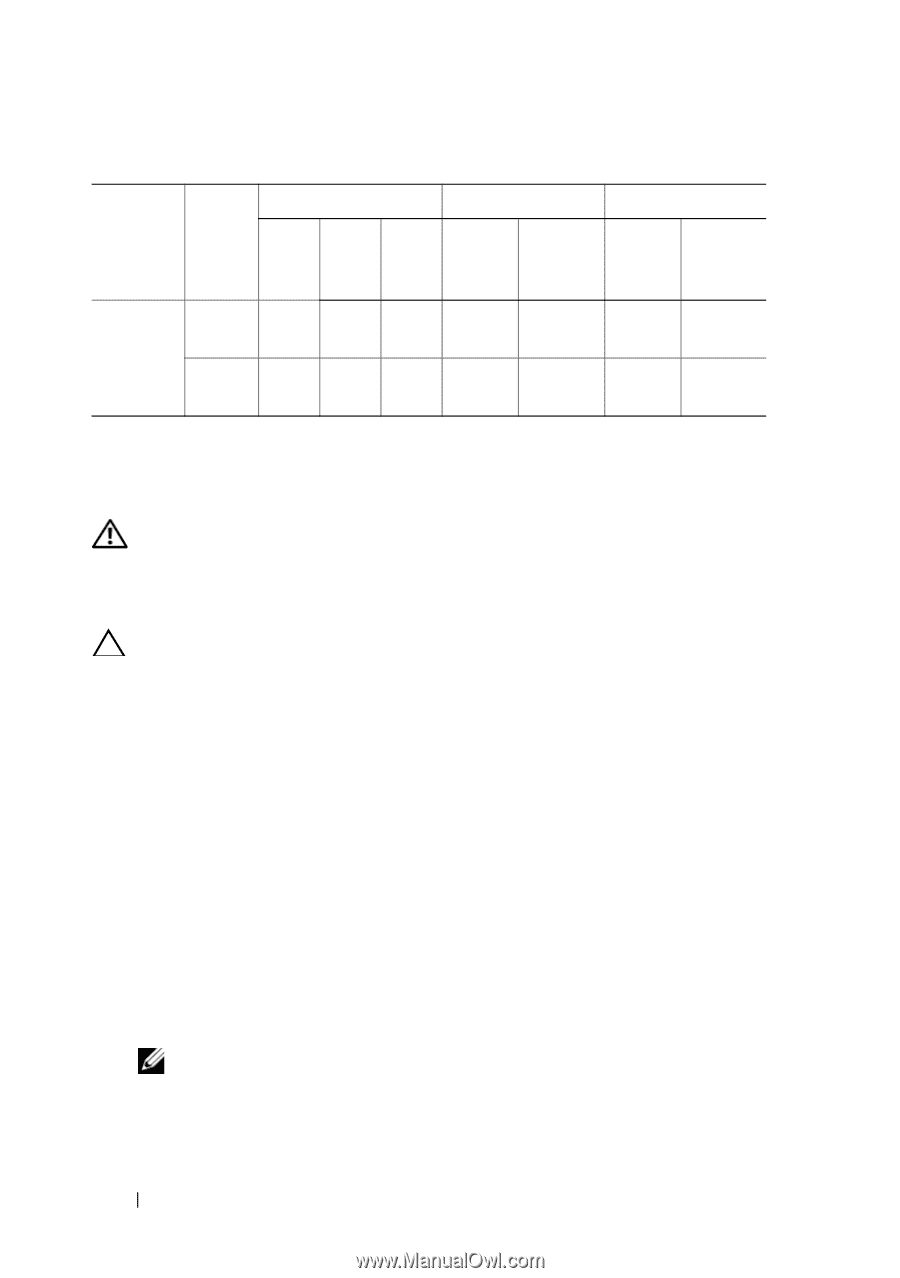
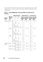
Table 3-3. Sample UDIMM Memory Configurations (Per Processor) Memory Mode Memory Sockets Memory Module 1 Size 4 2 5 3 6 Single Processor Dual Processor Physical Available Physical Available Memory Memory Memory Memory (GB) (GB) (GB) (GB) Mirroring 1-GB vacant X X 2 1 4 2 X XX X 4 2 8 4 2-GB vacant X X 4 X XX X 8 2 8 4 4 16 8 1. Requires x4- or x8-based memory modules. Installing Memory Modules WARNING: The memory modules are hot to the touch for some time after the system has been powered down. Allow time for the memory modules to cool before handling them. Handle the memory modules by the card edges and avoid touching the components on the memory module. CAUTION: To ensure proper system cooling, memory-module blanks must be installed in any memory socket that is not occupied. Remove memory-module blanks only if you intend to install memory in those sockets. 1 Turn off the system, including any attached peripherals, and disconnect the system from the electrical outlet and peripherals. Open the system. See "Opening the System." 2 Remove the expansion card stabilizer. See "Removing the Expansion Card Stabilizer." 3 Remove the cooling shroud. See "Removing the Cooling Shroud." 4 Locate the memory module sockets. See Figure 6-1. 5 Remove the memory-module blanks from the sockets in which you plan to install memory modules: Press down and out on the ejectors on each end of the socket until the memory-module blank pops out of the socket. See Figure 3-20. NOTE: Make sure to retain any removed memory-module blanks for future use. 128 Installing System Components
-
 1
1 -
2
-
3
-
4
-
5
-
6
-
7
-
8
-
9
-
10
-
11
-
12
-
13
-
14
-
15
-
16
-
17
-
18
-
19
-
20
-
21
-
22
-
23
-
24
-
25
-
26
-
27
-
28
-
29
-
30
-
31
-
32
-
33
-
34
-
35
-
36
-
37
-
38
-
39
-
40
-
41
-
42
-
43
-
44
-
45
-
46
-
47
-
48
-
49
-
50
-
51
-
52
-
53
-
54
-
55
-
56
-
57
-
58
-
59
-
60
-
61
-
62
-
63
-
64
-
65
-
66
-
67
-
68
-
69
-
70
-
71
-
72
-
73
-
74
-
75
-
76
-
77
-
78
-
79
-
80
-
81
-
82
-
83
-
84
-
85
-
86
-
87
-
88
-
89
-
90
-
91
-
92
-
93
-
94
-
95
-
96
-
97
-
98
-
99
-
100
-
101
-
102
-
103
-
104
-
105
-
106
-
107
-
108
-
109
-
110
-
111
-
112
-
113
-
114
-
115
-
116
-
117
-
118
-
119
-
120
-
121
-
122
-
 123
123 -
 124
124 -
 125
125 -
 126
126 -
 127
127 -
 128
128 -
 129
129 -
 130
130 -
 131
131 -
 132
132 -
 133
133 -
134
-
135
-
136
-
137
-
138
-
139
-
140
-
141
-
142
-
143
-
144
-
145
-
146
-
147
-
148
-
149
-
150
-
151
-
152
-
153
-
154
-
155
-
156
-
157
-
158
-
159
-
160
-
161
-
162
-
163
-
164
-
165
-
166
-
167
-
168
-
169
-
170
-
171
-
172
-
173
-
174
-
175
-
176
-
177
-
178
-
179
-
180
-
181
-
182
-
183
-
184
-
185
-
186
-
187
-
188
-
189
-
190
-
191
-
192
-
193
-
194
-
195
-
196
-
197
-
198
-
199
-
200
-
201
-
202
-
203
-
204
-
205
-
206
 |
 |