Dell PowerEdge T610 Hardware Owner's Manual - Page 79
Front Bezel, Removing the Front Bezel - chassis access
 |
View all Dell PowerEdge T610 manuals
Add to My Manuals
Save this manual to your list of manuals |
Page 79 highlights
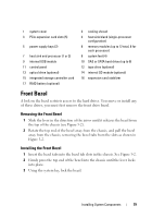
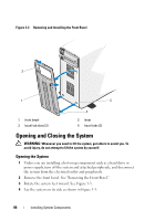
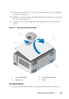
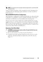
1 system cover 3 PCIe expansion card slots (5) 5 power supply bays (2) 7 heat sink and processor (1 or 2) 9 internal USB module 11 control panel 13 optical drive (optional) 15 integrated storage controller card 17 RAID battery (optional) 2 cooling shroud 4 heat sink blank (single-processor configuration) 6 memory modules (up to 12 total, 6 for each processor) 8 system feet (4) 10 SAS or SATA hard drives (up to 8) 12 tape drive (optional) 14 internal SD module (optional) 16 expansion card stabilizer Front Bezel A lock on the bezel restricts access to the hard drives. To remove or install any of these drives, you must first remove the front drive bezel. Removing the Front Bezel 1 Slide the lever in the direction of the arrow until it releases the bezel from the top of the chassis (see Figure 3-2). 2 Rotate the top end of the bezel away from the chassis, and pull the bezel away from the chassis, removing the bezel tabs from the slots as shown in Figure 3-2. Installing the Front Bezel 1 Insert the bezel tabs into the bezel tab slots in the chassis. See Figure 3-2. 2 Firmly press the top end of the bezel into the chassis until the lever locks into place. 3 Using the system key, lock the bezel. Installing System Components 79
-
 1
1 -
2
-
3
-
4
-
5
-
6
-
7
-
8
-
9
-
10
-
11
-
12
-
13
-
14
-
15
-
16
-
17
-
18
-
19
-
20
-
21
-
22
-
23
-
24
-
25
-
26
-
27
-
28
-
29
-
30
-
31
-
32
-
33
-
34
-
35
-
36
-
37
-
38
-
39
-
40
-
41
-
42
-
43
-
44
-
45
-
46
-
47
-
48
-
49
-
50
-
51
-
52
-
53
-
54
-
55
-
56
-
57
-
58
-
59
-
60
-
61
-
62
-
63
-
64
-
65
-
66
-
67
-
68
-
69
-
70
-
71
-
72
-
73
-
 74
74 -
 75
75 -
 76
76 -
 77
77 -
 78
78 -
 79
79 -
 80
80 -
 81
81 -
 82
82 -
 83
83 -
 84
84 -
85
-
86
-
87
-
88
-
89
-
90
-
91
-
92
-
93
-
94
-
95
-
96
-
97
-
98
-
99
-
100
-
101
-
102
-
103
-
104
-
105
-
106
-
107
-
108
-
109
-
110
-
111
-
112
-
113
-
114
-
115
-
116
-
117
-
118
-
119
-
120
-
121
-
122
-
123
-
124
-
125
-
126
-
127
-
128
-
129
-
130
-
131
-
132
-
133
-
134
-
135
-
136
-
137
-
138
-
139
-
140
-
141
-
142
-
143
-
144
-
145
-
146
-
147
-
148
-
149
-
150
-
151
-
152
-
153
-
154
-
155
-
156
-
157
-
158
-
159
-
160
-
161
-
162
-
163
-
164
-
165
-
166
-
167
-
168
-
169
-
170
-
171
-
172
-
173
-
174
-
175
-
176
-
177
-
178
-
179
-
180
-
181
-
182
-
183
-
184
-
185
-
186
-
187
-
188
-
189
-
190
-
191
-
192
-
193
-
194
-
195
-
196
-
197
-
198
-
199
-
200
-
201
-
202
-
203
-
204
-
205
-
206
 |
 |