Dell PowerEdge T610 Hardware Owner's Manual - Page 149
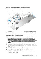
Disconnect the cables from the J_BB_SIG, J_BB_PWR1, and J_BB_PWR1, Three power cables from the J_PWR1
 |
View all Dell PowerEdge T610 manuals
Add to My Manuals
Save this manual to your list of manuals |
Page 149 highlights
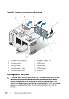
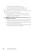
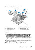
3 Remove the expansion card stabilizer. See "Removing the Expansion Card Stabilizer." 4 Remove the cooling shroud. See "Removing the Cooling Shroud." 5 Remove the NIC hardware key, if present. See Figure 6-1 for the ISCSI_KEY socket location. 6 Remove the integrated storage controller card. See "Removing an Integrated Storage Controller Card." 7 If applicable, remove all expansion cards and any attached cables. See "Removing an Expansion Card." 8 If applicable, remove the iDRAC6 Enterprise card. See "Removing the iDRAC6 Enterprise Card." 9 Remove all memory modules and memory-module blanks. See "Removing Memory Modules." NOTE: Record the memory-module socket locations to ensure proper reinstallation of the memory modules. WARNING: The processor and heat sink can become extremely hot. Allow sufficient time for the processor and heat sink to cool before handling. 10 Remove any installed heat sinks, processors, and heat-sink blanks. See "Removing a Processor." 11 Remove the SAS backplane from the system. See "Removing the SAS Backplane." 12 Remove the expansion card stabilizer bracket. Pull the blue release lever, and slide the expansion card stabilizer bracket up and out of the chassis. See Figure 3-27. 13 Disconnect the cables from the J_BB_SIG, J_BB_PWR1, and J_BB_PWR1 connectors on the power distribution board. See Figure 6-3 for connector locations. 14 Depending on your configuration, disconnect the following cables from the system board. See Figure 6-1 for connector locations. • Three power cables from the J_PWR1, J_PWR2, and J_PDB connectors • Control panel cable from the CTRL_PNL connector • SATA cable(s) from the SATA connector(s) Installing System Components 149
-
 1
1 -
2
-
3
-
4
-
5
-
6
-
7
-
8
-
9
-
10
-
11
-
12
-
13
-
14
-
15
-
16
-
17
-
18
-
19
-
20
-
21
-
22
-
23
-
24
-
25
-
26
-
27
-
28
-
29
-
30
-
31
-
32
-
33
-
34
-
35
-
36
-
37
-
38
-
39
-
40
-
41
-
42
-
43
-
44
-
45
-
46
-
47
-
48
-
49
-
50
-
51
-
52
-
53
-
54
-
55
-
56
-
57
-
58
-
59
-
60
-
61
-
62
-
63
-
64
-
65
-
66
-
67
-
68
-
69
-
70
-
71
-
72
-
73
-
74
-
75
-
76
-
77
-
78
-
79
-
80
-
81
-
82
-
83
-
84
-
85
-
86
-
87
-
88
-
89
-
90
-
91
-
92
-
93
-
94
-
95
-
96
-
97
-
98
-
99
-
100
-
101
-
102
-
103
-
104
-
105
-
106
-
107
-
108
-
109
-
110
-
111
-
112
-
113
-
114
-
115
-
116
-
117
-
118
-
119
-
120
-
121
-
122
-
123
-
124
-
125
-
126
-
127
-
128
-
129
-
130
-
131
-
132
-
133
-
134
-
135
-
136
-
137
-
138
-
139
-
140
-
141
-
142
-
143
-
 144
144 -
 145
145 -
 146
146 -
 147
147 -
 148
148 -
 149
149 -
 150
150 -
 151
151 -
 152
152 -
 153
153 -
 154
154 -
155
-
156
-
157
-
158
-
159
-
160
-
161
-
162
-
163
-
164
-
165
-
166
-
167
-
168
-
169
-
170
-
171
-
172
-
173
-
174
-
175
-
176
-
177
-
178
-
179
-
180
-
181
-
182
-
183
-
184
-
185
-
186
-
187
-
188
-
189
-
190
-
191
-
192
-
193
-
194
-
195
-
196
-
197
-
198
-
199
-
200
-
201
-
202
-
203
-
204
-
205
-
206
 |
 |
