Dell PowerEdge T610 Hardware Owner's Manual - Page 21
Power Indicator Codes - video card
 |
View all Dell PowerEdge T610 manuals
Add to My Manuals
Save this manual to your list of manuals |
Page 21 highlights
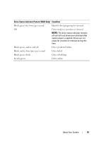
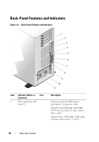
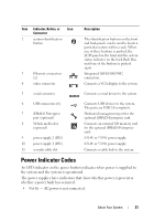
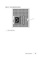
Item Indicator, Button, or Icon Connector 2 system identification button 3 Ethernet connectors (2) 4 video connector Description The identification buttons on the front and back panels can be used to locate a particular system within a rack. When one of these buttons is pushed, the LCD panel on the front and the system status indicator on the back flash blue until one of the buttons is pushed again. Integrated 10/100/1000 NIC connectors. Connects a VGA display to the system. 5 serial connector Connects a serial device to the system. 6 USB connectors (6) 7 iDRAC6 Enterprise port (optional) 8 VFlash media slot (optional) 9 power supply 2 (PS2) 10 power supply 1 (PS1) 11 security cable slot Connects USB devices to the system. The ports are USB 2.0-complaint. Dedicated management port for the optional iDRAC6 Enterprise card. Connects an external SD memory card for the optional iDRAC6 Enterprise card. 870-W or 570-W power supply. 870-W or 570-W power supply. Connects a cable lock to the system. Power Indicator Codes An LED indicator on the power button indicates when power is supplied to the system and the system is operational. The power supplies have indicators that show whether power is present or whether a power fault has occurred. • Not lit - AC power is not connected. About Your System 21
-
 1
1 -
2
-
3
-
4
-
5
-
6
-
7
-
8
-
9
-
10
-
11
-
12
-
13
-
14
-
15
-
 16
16 -
 17
17 -
 18
18 -
 19
19 -
 20
20 -
 21
21 -
 22
22 -
 23
23 -
 24
24 -
 25
25 -
 26
26 -
27
-
28
-
29
-
30
-
31
-
32
-
33
-
34
-
35
-
36
-
37
-
38
-
39
-
40
-
41
-
42
-
43
-
44
-
45
-
46
-
47
-
48
-
49
-
50
-
51
-
52
-
53
-
54
-
55
-
56
-
57
-
58
-
59
-
60
-
61
-
62
-
63
-
64
-
65
-
66
-
67
-
68
-
69
-
70
-
71
-
72
-
73
-
74
-
75
-
76
-
77
-
78
-
79
-
80
-
81
-
82
-
83
-
84
-
85
-
86
-
87
-
88
-
89
-
90
-
91
-
92
-
93
-
94
-
95
-
96
-
97
-
98
-
99
-
100
-
101
-
102
-
103
-
104
-
105
-
106
-
107
-
108
-
109
-
110
-
111
-
112
-
113
-
114
-
115
-
116
-
117
-
118
-
119
-
120
-
121
-
122
-
123
-
124
-
125
-
126
-
127
-
128
-
129
-
130
-
131
-
132
-
133
-
134
-
135
-
136
-
137
-
138
-
139
-
140
-
141
-
142
-
143
-
144
-
145
-
146
-
147
-
148
-
149
-
150
-
151
-
152
-
153
-
154
-
155
-
156
-
157
-
158
-
159
-
160
-
161
-
162
-
163
-
164
-
165
-
166
-
167
-
168
-
169
-
170
-
171
-
172
-
173
-
174
-
175
-
176
-
177
-
178
-
179
-
180
-
181
-
182
-
183
-
184
-
185
-
186
-
187
-
188
-
189
-
190
-
191
-
192
-
193
-
194
-
195
-
196
-
197
-
198
-
199
-
200
-
201
-
202
-
203
-
204
-
205
-
206
 |
 |