HP ML370 HP ProLiant ML370 Generation 3 Setup and Installation Guide - Page 167
Hot-Plug Power Supplies, Power On/Standby Button/LED Assembly, External Cabling Configurations
 |
UPC - 613326765616
View all HP ML370 manuals
Add to My Manuals
Save this manual to your list of manuals |
Page 167 highlights
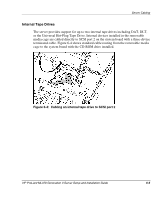
Server Cabling Hot-Plug Power Supplies The server includes a hot-plug power supply and available power supply bay for 1+1 redundancy. Each power supply connects directly to the power supply backplane. For instructions on installing a redundant power supply, refer to Chapter 3, "Installing Hardware Options" or refer to the hardware configuration and installation instructions that ship with the server. For information about internal power connections or the power supply backplane, refer the maintenance and service guide for the server. Power On/Standby Button/LED Assembly The server includes a Power On/Standby button/LED assembly that connects directly to the system board. For instructions on replacing the Power On/Standby button/LED assembly, refer to the maintenance and service guide for the server. External Cabling Configurations The following sections describe cabling configurations for peripheral devices and external storage devices supported by the server. SCSI Cabling Guidelines The external VHDCI SCSI connector is located on the rear panel of the server as shown in Figure 6-9. This interface enables you to install and manage external SCSI devices with the system standard Integrated Dual Channel Ultra3 SCSI controller. IMPORTANT: Connect either external devices to the external VHDCI SCSI connector or internal devices to SCSI port 2. The server does not support both internal and external devices on the same channel at the same time. 6-10 HP ProLiant ML370 Generation 3 Server Setup and Installation Guide
-
 1
1 -
2
-
3
-
4
-
5
-
6
-
7
-
8
-
9
-
10
-
11
-
12
-
13
-
14
-
15
-
16
-
17
-
18
-
19
-
20
-
21
-
22
-
23
-
24
-
25
-
26
-
27
-
28
-
29
-
30
-
31
-
32
-
33
-
34
-
35
-
36
-
37
-
38
-
39
-
40
-
41
-
42
-
43
-
44
-
45
-
46
-
47
-
48
-
49
-
50
-
51
-
52
-
53
-
54
-
55
-
56
-
57
-
58
-
59
-
60
-
61
-
62
-
63
-
64
-
65
-
66
-
67
-
68
-
69
-
70
-
71
-
72
-
73
-
74
-
75
-
76
-
77
-
78
-
79
-
80
-
81
-
82
-
83
-
84
-
85
-
86
-
87
-
88
-
89
-
90
-
91
-
92
-
93
-
94
-
95
-
96
-
97
-
98
-
99
-
100
-
101
-
102
-
103
-
104
-
105
-
106
-
107
-
108
-
109
-
110
-
111
-
112
-
113
-
114
-
115
-
116
-
117
-
118
-
119
-
120
-
121
-
122
-
123
-
124
-
125
-
126
-
127
-
128
-
129
-
130
-
131
-
132
-
133
-
134
-
135
-
136
-
137
-
138
-
139
-
140
-
141
-
142
-
143
-
144
-
145
-
146
-
147
-
148
-
149
-
150
-
151
-
152
-
153
-
154
-
155
-
156
-
157
-
158
-
159
-
160
-
161
-
 162
162 -
 163
163 -
 164
164 -
 165
165 -
 166
166 -
 167
167 -
 168
168 -
 169
169 -
 170
170 -
 171
171 -
 172
172 -
173
-
174
-
175
-
176
-
177
-
178
-
179
-
180
-
181
-
182
-
183
-
184
-
185
-
186
-
187
-
188
-
189
-
190
-
191
-
192
-
193
-
194
-
195
-
196
-
197
-
198
-
199
-
200
-
201
-
202
-
203
-
204
-
205
-
206
-
207
-
208
-
209
-
210
-
211
-
212
-
213
-
214
-
215
-
216
-
217
-
218
-
219
-
220
-
221
-
222
-
223
-
224
-
225
-
226
-
227
-
228
-
229
-
230
-
231
-
232
-
233
-
234
-
235
-
236
-
237
-
238
-
239
-
240
-
241
-
242
-
243
-
244
-
245
-
246
-
247
-
248
-
249
-
250
-
251
-
252
-
253
-
254
-
255
-
256
-
257
-
258
-
259
-
260
-
261
-
262
-
263
 |
 |
