HP ML370 HP ProLiant ML370 Generation 3 Setup and Installation Guide - Page 227
Front Panel LEDs, E-1, Table E-1
 |
UPC - 613326765616
View all HP ML370 manuals
Add to My Manuals
Save this manual to your list of manuals |
Page 227 highlights
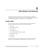
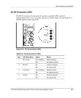
LED Indicators and Switches Front Panel LEDs The set of five LEDs on the front of the server indicates system health. Figure E-1 and Table E-1 identify and describe the location and function of each LED. Figure E-1: Front panel LEDs Table E-1: Front Panel LEDs Item 1 2 Description UID switch and LED Internal system health LED Status Blue Flashing blue Off Green Amber Red Off Means Activated System being managed remotely Deactivated Normal (system on) System degraded System critical Normal (system off) continued E-2 HP ProLiant ML370 Generation 3 Server Setup and Installation Guide
-
 1
1 -
2
-
3
-
4
-
5
-
6
-
7
-
8
-
9
-
10
-
11
-
12
-
13
-
14
-
15
-
16
-
17
-
18
-
19
-
20
-
21
-
22
-
23
-
24
-
25
-
26
-
27
-
28
-
29
-
30
-
31
-
32
-
33
-
34
-
35
-
36
-
37
-
38
-
39
-
40
-
41
-
42
-
43
-
44
-
45
-
46
-
47
-
48
-
49
-
50
-
51
-
52
-
53
-
54
-
55
-
56
-
57
-
58
-
59
-
60
-
61
-
62
-
63
-
64
-
65
-
66
-
67
-
68
-
69
-
70
-
71
-
72
-
73
-
74
-
75
-
76
-
77
-
78
-
79
-
80
-
81
-
82
-
83
-
84
-
85
-
86
-
87
-
88
-
89
-
90
-
91
-
92
-
93
-
94
-
95
-
96
-
97
-
98
-
99
-
100
-
101
-
102
-
103
-
104
-
105
-
106
-
107
-
108
-
109
-
110
-
111
-
112
-
113
-
114
-
115
-
116
-
117
-
118
-
119
-
120
-
121
-
122
-
123
-
124
-
125
-
126
-
127
-
128
-
129
-
130
-
131
-
132
-
133
-
134
-
135
-
136
-
137
-
138
-
139
-
140
-
141
-
142
-
143
-
144
-
145
-
146
-
147
-
148
-
149
-
150
-
151
-
152
-
153
-
154
-
155
-
156
-
157
-
158
-
159
-
160
-
161
-
162
-
163
-
164
-
165
-
166
-
167
-
168
-
169
-
170
-
171
-
172
-
173
-
174
-
175
-
176
-
177
-
178
-
179
-
180
-
181
-
182
-
183
-
184
-
185
-
186
-
187
-
188
-
189
-
190
-
191
-
192
-
193
-
194
-
195
-
196
-
197
-
198
-
199
-
200
-
201
-
202
-
203
-
204
-
205
-
206
-
207
-
208
-
209
-
210
-
211
-
212
-
213
-
214
-
215
-
216
-
217
-
218
-
219
-
220
-
221
-
 222
222 -
 223
223 -
 224
224 -
 225
225 -
 226
226 -
 227
227 -
 228
228 -
 229
229 -
 230
230 -
 231
231 -
 232
232 -
233
-
234
-
235
-
236
-
237
-
238
-
239
-
240
-
241
-
242
-
243
-
244
-
245
-
246
-
247
-
248
-
249
-
250
-
251
-
252
-
253
-
254
-
255
-
256
-
257
-
258
-
259
-
260
-
261
-
262
-
263
 |
 |

LED Indicators and Switches
E-2
HP ProLiant ML370 Generation 3 Server Setup and Installation Guide
Front Panel LEDs
The set of five LEDs on the front of the server indicates system health. Figure E-1
and Table E-1 identify and describe the location and function of each LED.
Figure E-1:
Front panel LEDs
Table E-1:
Front Panel LEDs
Item
Description
Status
Means
Blue
Activated
Flashing
blue
System being managed
remotely
1
UID switch and LED
Off
Deactivated
Green
Normal (system on)
Amber
System degraded
Red
System critical
2
Internal system health
LED
Off
Normal (system off)
continued