HP ML370 HP ProLiant ML370 Generation 3 Setup and Installation Guide - Page 242
System Identification Switch, System Configuration Settings
 |
UPC - 613326765616
View all HP ML370 manuals
Add to My Manuals
Save this manual to your list of manuals |
Page 242 highlights
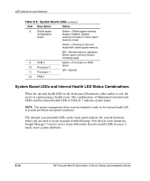
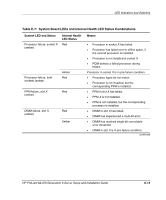
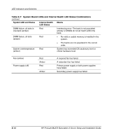
LED Indicators and Switches System Identification Switch The system identification switch (SW2) is a three-position switch that identifies the operational configuration of the server. This switch is set to the correct configuration for the server by default. Table E-10 identifies switch settings and positions. CAUTION: Do not alter the default setting for the server. Doing so causes improper server operation. Table E-10: System Identification Switch (SW2) Position 1 2 3 Description ID0 ID1 ID2 Settings for 2.4-GHz and 2.8-GHz models Off Off Off Settings for 3.06-GHz and above models Off Off On System Configuration Settings It may be necessary at some time to clear and reset system configuration settings. When the system maintenance switch position 6 is set to the on position, the system is prepared to erase all system configuration settings from both CMOS and NVRAM. For additional information about locating the switch and switch settings, refer to "System Maintenance Switch" in this appendix. The default setting for all positions is Off. IMPORTANT: Clearing CMOS and/or (NVRAM) deletes configuration information. Refer to Chapter 7, "Server Configuration and Utilities," for complete instructions on configuring the server. To erase all system configuration settings: 1. Power down the server. 2. Remove the access panel. HP ProLiant ML370 Generation 3 Server Setup and Installation Guide E-17
-
 1
1 -
2
-
3
-
4
-
5
-
6
-
7
-
8
-
9
-
10
-
11
-
12
-
13
-
14
-
15
-
16
-
17
-
18
-
19
-
20
-
21
-
22
-
23
-
24
-
25
-
26
-
27
-
28
-
29
-
30
-
31
-
32
-
33
-
34
-
35
-
36
-
37
-
38
-
39
-
40
-
41
-
42
-
43
-
44
-
45
-
46
-
47
-
48
-
49
-
50
-
51
-
52
-
53
-
54
-
55
-
56
-
57
-
58
-
59
-
60
-
61
-
62
-
63
-
64
-
65
-
66
-
67
-
68
-
69
-
70
-
71
-
72
-
73
-
74
-
75
-
76
-
77
-
78
-
79
-
80
-
81
-
82
-
83
-
84
-
85
-
86
-
87
-
88
-
89
-
90
-
91
-
92
-
93
-
94
-
95
-
96
-
97
-
98
-
99
-
100
-
101
-
102
-
103
-
104
-
105
-
106
-
107
-
108
-
109
-
110
-
111
-
112
-
113
-
114
-
115
-
116
-
117
-
118
-
119
-
120
-
121
-
122
-
123
-
124
-
125
-
126
-
127
-
128
-
129
-
130
-
131
-
132
-
133
-
134
-
135
-
136
-
137
-
138
-
139
-
140
-
141
-
142
-
143
-
144
-
145
-
146
-
147
-
148
-
149
-
150
-
151
-
152
-
153
-
154
-
155
-
156
-
157
-
158
-
159
-
160
-
161
-
162
-
163
-
164
-
165
-
166
-
167
-
168
-
169
-
170
-
171
-
172
-
173
-
174
-
175
-
176
-
177
-
178
-
179
-
180
-
181
-
182
-
183
-
184
-
185
-
186
-
187
-
188
-
189
-
190
-
191
-
192
-
193
-
194
-
195
-
196
-
197
-
198
-
199
-
200
-
201
-
202
-
203
-
204
-
205
-
206
-
207
-
208
-
209
-
210
-
211
-
212
-
213
-
214
-
215
-
216
-
217
-
218
-
219
-
220
-
221
-
222
-
223
-
224
-
225
-
226
-
227
-
228
-
229
-
230
-
231
-
232
-
233
-
234
-
235
-
236
-
 237
237 -
 238
238 -
 239
239 -
 240
240 -
 241
241 -
 242
242 -
 243
243 -
 244
244 -
 245
245 -
 246
246 -
 247
247 -
248
-
249
-
250
-
251
-
252
-
253
-
254
-
255
-
256
-
257
-
258
-
259
-
260
-
261
-
262
-
263
 |
 |
