HP NetServer AA 4000 HP AA HP Netserver 4000 Reference Guide - Page 13
The Data Link A port is
 |
View all HP NetServer AA 4000 manuals
Add to My Manuals
Save this manual to your list of manuals |
Page 13 highlights
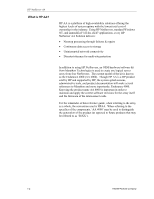
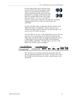
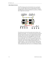
Ch 1: Architecture Overview and Terminology The term tuple simply refers to the pair of one CE and one IOP connected through one SSDL. Tuples are important during installation and when trying to determine the status of the array. By default, CE1 attempts comminucation with IOP1 first, and then IOP2 in the event of IOP1 being unavailable. However, even though the CEs try to communicate within their own tuple first, cross-tuple communications will occur when one of the NetServers is unavailable. As long as the MIC cables are attached to the slot correctly on the SSDLs, the tuples are "predefined." There is only one way to configure the tuples, and CE1 and IOP1 will always be tuple 1; the same is tru for CE2, IOP2, and tuple 2. All of the MICs are the same. What distinguishes CE from IOP, and CE1 from CE2, is the position of the cable on the SSDL and the SSDL itself. Though the SSDLs are identical in appearance, there is a slight difference in the inside of the SSDL that distinguishes between SSDL1 and SSDL2. The following is a rear view of the SSDL where the MIC cables are plugged. Note that there are two 100 pin serial ports for the MIC cable, but there are specifically labeled for CE or IOP. The Data Link A port is for the Tuple Link cable (similar to the MIC cable) that goes to the other SSDL. Network Server Division 1-7
-
 1
1 -
2
-
3
-
4
-
5
-
6
-
7
-
 8
8 -
 9
9 -
 10
10 -
 11
11 -
 12
12 -
 13
13 -
 14
14 -
 15
15 -
 16
16 -
 17
17 -
 18
18 -
19
-
20
-
21
-
22
-
23
-
24
-
25
-
26
-
27
-
28
-
29
-
30
-
31
-
32
-
33
-
34
-
35
-
36
-
37
-
38
-
39
-
40
-
41
-
42
-
43
-
44
-
45
-
46
-
47
-
48
-
49
-
50
-
51
-
52
-
53
-
54
-
55
-
56
-
57
-
58
-
59
-
60
-
61
-
62
-
63
-
64
-
65
-
66
-
67
-
68
-
69
-
70
-
71
-
72
-
73
-
74
-
75
-
76
-
77
-
78
-
79
-
80
-
81
-
82
-
83
-
84
-
85
-
86
-
87
-
88
-
89
-
90
-
91
-
92
-
93
-
94
-
95
-
96
-
97
-
98
-
99
-
100
-
101
-
102
-
103
-
104
-
105
-
106
-
107
-
108
-
109
-
110
-
111
-
112
-
113
-
114
-
115
-
116
-
117
-
118
-
119
-
120
-
121
-
122
-
123
-
124
-
125
-
126
-
127
-
128
-
129
-
130
-
131
-
132
-
133
-
134
-
135
-
136
-
137
-
138
-
139
-
140
-
141
-
142
 |
 |