HP NetServer AA 4000 HP AA HP Netserver 4000 Reference Guide - Page 77
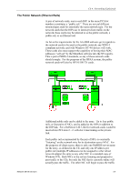
Public Network to IOP to CE and Back.
 |
View all HP NetServer AA 4000 manuals
Add to My Manuals
Save this manual to your list of manuals |
Page 77 highlights
Ch 4: Networking Explaineds segment B via a different path, then the MTCETHRs need to reflect that in their addressing. The bindings to each MTCETHR consist of the appropriate traditional network protocol. Public Network to IOP to CE and Back. Now that all of the protocols and bindings are in place, a "trace" of a typical network request can be traced through the tuple. 1. Client traffic comes through the hub and is seen by all public rails NICs for both IOPs that are on the local LAN segment (assuming the same collision domain). 2. The public network card receives the traffic and immediately passes it to the MIC. There is no analysis or breakdown of the packet. 3. The packet is routed from the MIC to the SSDL for tuple 1. 4. The packet is received by the SSDL1 and prepared to be sent out again. 5. The SSDL will send the packet to the MICs of both CEs (the path to CE2 is routed through SSDL2). 6. The CE's virtual network adapter will receive the packet from the MIC as if it were any other LAN traffic and its adapter existed directly on the LAN. Whatever the network request, the CE will generate responses to be sent through the MICs to the IOPs. Network Server Division 4-11
-
 1
1 -
2
-
3
-
4
-
5
-
6
-
7
-
8
-
9
-
10
-
11
-
12
-
13
-
14
-
15
-
16
-
17
-
18
-
19
-
20
-
21
-
22
-
23
-
24
-
25
-
26
-
27
-
28
-
29
-
30
-
31
-
32
-
33
-
34
-
35
-
36
-
37
-
38
-
39
-
40
-
41
-
42
-
43
-
44
-
45
-
46
-
47
-
48
-
49
-
50
-
51
-
52
-
53
-
54
-
55
-
56
-
57
-
58
-
59
-
60
-
61
-
62
-
63
-
64
-
65
-
66
-
67
-
68
-
69
-
70
-
71
-
 72
72 -
 73
73 -
 74
74 -
 75
75 -
 76
76 -
 77
77 -
 78
78 -
 79
79 -
 80
80 -
 81
81 -
 82
82 -
83
-
84
-
85
-
86
-
87
-
88
-
89
-
90
-
91
-
92
-
93
-
94
-
95
-
96
-
97
-
98
-
99
-
100
-
101
-
102
-
103
-
104
-
105
-
106
-
107
-
108
-
109
-
110
-
111
-
112
-
113
-
114
-
115
-
116
-
117
-
118
-
119
-
120
-
121
-
122
-
123
-
124
-
125
-
126
-
127
-
128
-
129
-
130
-
131
-
132
-
133
-
134
-
135
-
136
-
137
-
138
-
139
-
140
-
141
-
142
 |
 |