HP NetServer AA 4000 HP AA HP Netserver 4000 Reference Guide - Page 33
Powering Up the HPAA System
 |
View all HP NetServer AA 4000 manuals
Add to My Manuals
Save this manual to your list of manuals |
Page 33 highlights
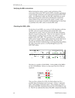
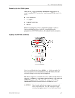
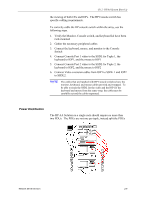
Ch 2: HPAA System Boot Up Powering Up the HPAA System There are up to eight components that need to be powered on in order to use the HPAA system (not counting any UPS devices in the rack): • Four NetServers • Two SSDLs • Console Switch Box • Monitor Before examining the power on sequence, first take a look at a typical rack implementation and how it is cabled from the perspectives of AA 4000 hardware, the console switch, and power. Cabling the AA 4000 hardware Network Server Division Once the peripherals have been added to the NetServers and all of the components are rack mounted, including the SSDLs, then the external cabling for the array can be completed. The above diagram is an overall view of the cables directly related to the array's availability. One cable is used for the IOP Link; this is an UTP CAT-5 patch cable. The rest of the cables are the 100-pin ribbon cable that interconnects the tuples through the SSDLs. CAUTION Place the tuple cables in their respective connectors and make a firm connection. Once the connection is made correctly, then tighten the screw about half a turn. Do not 2-7
-
 1
1 -
2
-
3
-
4
-
5
-
6
-
7
-
8
-
9
-
10
-
11
-
12
-
13
-
14
-
15
-
16
-
17
-
18
-
19
-
20
-
21
-
22
-
23
-
24
-
25
-
26
-
27
-
 28
28 -
 29
29 -
 30
30 -
 31
31 -
 32
32 -
 33
33 -
 34
34 -
 35
35 -
 36
36 -
 37
37 -
 38
38 -
39
-
40
-
41
-
42
-
43
-
44
-
45
-
46
-
47
-
48
-
49
-
50
-
51
-
52
-
53
-
54
-
55
-
56
-
57
-
58
-
59
-
60
-
61
-
62
-
63
-
64
-
65
-
66
-
67
-
68
-
69
-
70
-
71
-
72
-
73
-
74
-
75
-
76
-
77
-
78
-
79
-
80
-
81
-
82
-
83
-
84
-
85
-
86
-
87
-
88
-
89
-
90
-
91
-
92
-
93
-
94
-
95
-
96
-
97
-
98
-
99
-
100
-
101
-
102
-
103
-
104
-
105
-
106
-
107
-
108
-
109
-
110
-
111
-
112
-
113
-
114
-
115
-
116
-
117
-
118
-
119
-
120
-
121
-
122
-
123
-
124
-
125
-
126
-
127
-
128
-
129
-
130
-
131
-
132
-
133
-
134
-
135
-
136
-
137
-
138
-
139
-
140
-
141
-
142
 |
 |