HP NetServer AA 4000 HP AA HP Netserver 4000 Reference Guide - Page 35
Power Distribution
 |
View all HP NetServer AA 4000 manuals
Add to My Manuals
Save this manual to your list of manuals |
Page 35 highlights
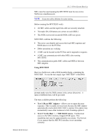
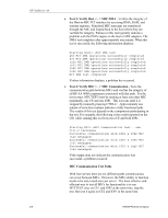
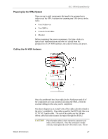
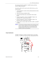
Ch 2: HPAA System Boot Up the viewing of both CEs and IOPs. The HP Console switch has specific cabling requirements. To correctly cable the HP console switch within the array, use the following steps. 1. Verify the Monitor, Console switch, and keyboard kit have been rack-mounted 2. Gather the necessary peripheral cables 3. Connect the keyboard, mouse, and monitor to the Console Switch 4. Connect Console Port 1 video to the SSDL for Tuple 1, the keyboard to IOP1, and the mouse to IOP1 5. Connect Console Port 2 video to the SSDL for Tuple 2, the keyboard to IOP2, and the mouse to IOP2 6. Connect Video extension cables from IOP1 to SSDL 1 and IOP2 to SSDL2. NOTE The cables that are bundled with HP Console switches have the monitor, keyboard, and mouse cables pre-tied and wrapped. To be able to reach the SSDL for the video and the IOP for the keyboard and mouse from the same wrap, the cable must be carefully cut and the cables separated. Power Distribution The HP AA Solution in a single rack should require no more than two PDUs. The PDUs are not one per tuple, instead split the PDUs Network Server Division 2-9
-
 1
1 -
2
-
3
-
4
-
5
-
6
-
7
-
8
-
9
-
10
-
11
-
12
-
13
-
14
-
15
-
16
-
17
-
18
-
19
-
20
-
21
-
22
-
23
-
24
-
25
-
26
-
27
-
28
-
29
-
 30
30 -
 31
31 -
 32
32 -
 33
33 -
 34
34 -
 35
35 -
 36
36 -
 37
37 -
 38
38 -
 39
39 -
 40
40 -
41
-
42
-
43
-
44
-
45
-
46
-
47
-
48
-
49
-
50
-
51
-
52
-
53
-
54
-
55
-
56
-
57
-
58
-
59
-
60
-
61
-
62
-
63
-
64
-
65
-
66
-
67
-
68
-
69
-
70
-
71
-
72
-
73
-
74
-
75
-
76
-
77
-
78
-
79
-
80
-
81
-
82
-
83
-
84
-
85
-
86
-
87
-
88
-
89
-
90
-
91
-
92
-
93
-
94
-
95
-
96
-
97
-
98
-
99
-
100
-
101
-
102
-
103
-
104
-
105
-
106
-
107
-
108
-
109
-
110
-
111
-
112
-
113
-
114
-
115
-
116
-
117
-
118
-
119
-
120
-
121
-
122
-
123
-
124
-
125
-
126
-
127
-
128
-
129
-
130
-
131
-
132
-
133
-
134
-
135
-
136
-
137
-
138
-
139
-
140
-
141
-
142
 |
 |