HP NetServer AA 4000 HP AA HP Netserver 4000 Reference Guide - Page 28
Compute
 |
View all HP NetServer AA 4000 manuals
Add to My Manuals
Save this manual to your list of manuals |
Page 28 highlights
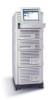
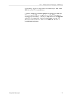
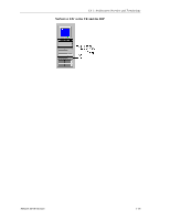
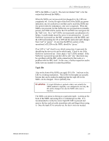
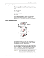
HP NetServer AA Verifying the MIC connections Before booting the system, a quick visual verification of the connections between the MICs and the SSDLs should be performed. A more through verification can be performed using the MTCTEST utility. It is important to make sure the MIC connections are good before powering up the system and re-checking the connections when a failure of any type occurs in the system. A quick visual inspection can save hours of needless troubleshooting if in fact there is a problem with a MIC cable or even the MIC itself. Checking the SSDL LEDs On the front of each SSDL are a series of LEDs that help verify that the MIC cards are in good working order and the MIC cable connections are correct. However, this is not the final verification that all is in good working order. There are rare instances when all LEDs indicate a working system, but there may still be a minor problem with a MIC cable. The occurrence is rare enough that the LEDs can be "trusted" and the cable connections can be ruled out as the cause of a problem when troubleshooting. But in the rare instance that all other troubleshooting is not pinpointing the problem, the cable connections can be re-verified through the use of the MTCTEST utility. The above is a graphic of both SSDLs. In the middle of the SSDLs are the LED indicators. Below is a close-up of how the LEDs are organized. Compute I/O Link 12 3 There are three columns for LEDs, the third column was for a possible future development and is not used. Column 1 represents tuple 1 and column 2 represents tuple 2. The Compute row shows the status of the MIC connections from the CEs to the SSDLs (1 and 2). The I/O row indicates the status of the MIC connections from the 2-2 Hewlett-Packard Company
-
 1
1 -
2
-
3
-
4
-
5
-
6
-
7
-
8
-
9
-
10
-
11
-
12
-
13
-
14
-
15
-
16
-
17
-
18
-
19
-
20
-
21
-
22
-
 23
23 -
 24
24 -
 25
25 -
 26
26 -
 27
27 -
 28
28 -
 29
29 -
 30
30 -
 31
31 -
 32
32 -
 33
33 -
34
-
35
-
36
-
37
-
38
-
39
-
40
-
41
-
42
-
43
-
44
-
45
-
46
-
47
-
48
-
49
-
50
-
51
-
52
-
53
-
54
-
55
-
56
-
57
-
58
-
59
-
60
-
61
-
62
-
63
-
64
-
65
-
66
-
67
-
68
-
69
-
70
-
71
-
72
-
73
-
74
-
75
-
76
-
77
-
78
-
79
-
80
-
81
-
82
-
83
-
84
-
85
-
86
-
87
-
88
-
89
-
90
-
91
-
92
-
93
-
94
-
95
-
96
-
97
-
98
-
99
-
100
-
101
-
102
-
103
-
104
-
105
-
106
-
107
-
108
-
109
-
110
-
111
-
112
-
113
-
114
-
115
-
116
-
117
-
118
-
119
-
120
-
121
-
122
-
123
-
124
-
125
-
126
-
127
-
128
-
129
-
130
-
131
-
132
-
133
-
134
-
135
-
136
-
137
-
138
-
139
-
140
-
141
-
142
 |
 |