Symantec 10521148 Implementation Guide - Page 45
Port groups and the management port on the bypass unit, Table 3-3, Connection, Bypass port
 |
View all Symantec 10521148 manuals
Add to My Manuals
Save this manual to your list of manuals |
Page 45 highlights
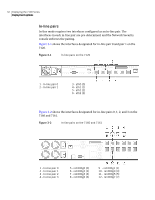
Figure 3-5 4 In-line Bypass unit Deploying the 7100 Series 37 Deployment options 1 - Serial port 2 - Mgmt USB 3 - Power Supply 1 4 - Power Supply 2 5 - Port group 0 6 - Port group 1 7 - Port group 2 8 - Port group 3 Port groups and the management port on the bypass unit Each bypass unit contains groups of ports called port groups. Each port group contains four ports that connect to the network and to the in-line pair ports on the appliance. Each bypass unit also has a USB port for communication with the appliance. The Net A port of each port group on the bypass unit is implemented as 10/100/1000Base-TX. It is a Medium Dependent Interface, crossed (MDIX). You may need a crossover cable to connect Net A to some devices. The Net B port of each port group is implemented as 10/100/1000Base-T (MDI). Consult the documentation for your network devices to determine whether they require crossover connections. You must supply at least four connections to each port group in use on the bypass unit, plus one USB connection per bypass unit. Table 3-3 describes these connections. Table 3-3 Connections needed for deploying bypass unit Connection Bypass port Description The appliance USB Mgmt USB port One side of the network Net A Connects to either USB port on the appliance. The two devices communicate over the USB connection. Connects to one side of the network that you are protecting. Net A is the Base-TX port (MDIX).
-
 1
1 -
2
-
3
-
4
-
5
-
6
-
7
-
8
-
9
-
10
-
11
-
12
-
13
-
14
-
15
-
16
-
17
-
18
-
19
-
20
-
21
-
22
-
23
-
24
-
25
-
26
-
27
-
28
-
29
-
30
-
31
-
32
-
33
-
34
-
35
-
36
-
37
-
38
-
39
-
 40
40 -
 41
41 -
 42
42 -
 43
43 -
 44
44 -
 45
45 -
 46
46 -
 47
47 -
 48
48 -
 49
49 -
 50
50 -
51
-
52
-
53
-
54
-
55
-
56
-
57
-
58
-
59
-
60
-
61
-
62
-
63
-
64
-
65
-
66
-
67
-
68
-
69
-
70
-
71
-
72
-
73
-
74
-
75
-
76
-
77
-
78
-
79
-
80
-
81
-
82
-
83
-
84
-
85
-
86
-
87
-
88
-
89
-
90
-
91
-
92
-
93
-
94
-
95
-
96
-
97
-
98
-
99
-
100
-
101
-
102
-
103
-
104
-
105
-
106
-
107
-
108
-
109
-
110
-
111
-
112
-
113
-
114
-
115
-
116
-
117
-
118
-
119
-
120
-
121
-
122
-
123
-
124
-
125
-
126
-
127
-
128
-
129
-
130
-
131
-
132
-
133
-
134
-
135
-
136
-
137
-
138
-
139
-
140
-
141
-
142
-
143
-
144
-
145
-
146
-
147
-
148
-
149
-
150
-
151
-
152
-
153
-
154
-
155
-
156
-
157
-
158
-
159
-
160
-
161
-
162
-
163
-
164
-
165
-
166
-
167
-
168
-
169
-
170
-
171
-
172
-
173
-
174
-
175
-
176
-
177
-
178
-
179
-
180
-
181
-
182
-
183
-
184
-
185
-
186
-
187
-
188
-
189
-
190
-
191
-
192
-
193
-
194
-
195
-
196
-
197
-
198
-
199
-
200
-
201
-
202
-
203
-
204
-
205
-
206
-
207
-
208
-
209
-
210
-
211
-
212
-
213
-
214
 |
 |
