Symantec 10521148 Implementation Guide - Page 47
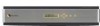
Front panel LEDs on the bypass unit, Table 3-4, Diagram, location, LED label, LED name
 |
View all Symantec 10521148 manuals
Add to My Manuals
Save this manual to your list of manuals |
Page 47 highlights
Deploying the 7100 Series 39 Deployment options result in link speed or duplex mismatches which could cause degraded performance or possible loss of connectivity. After connecting the bypass unit to a 7100 Series appliance, you should verify the link speed and duplex parameters for all interfaces in the port group. To verify the link parameters for Net A and Net B, log on to the connected network devices and display the status for the connected interfaces. Ensure that the connected interfaces are configured for auto-negotiation of link parameters. To verify the link parameters for App A and App B, use the Network Security console. After starting a sensor on the corresponding in-line pair, you can view the link parameters by clicking each interface object in the in-line pair. See "Interface status parameters" on page 133. The parameter values for all interfaces in the port group should be the same when the bypass unit is in online mode. For a 2 In-line Bypass unit connected to a 7120, all interfaces should auto-negotiate to 100 Mbps in online mode. However, when Net A and Net B on a 2 In-line Bypass unit are connected to gigabit interfaces on both network devices, the bypass unit can run at up to 1000 Mbps in bypass mode. Front panel LEDs on the bypass unit Both In-line Bypass units share a common front panel that contains a number of status LEDs. Figure 3-6 shows the bypass unit front panel LED configuration. Figure 3-6 Bypass unit front panel LEDs 4 5 0 1236 7 Table 3-4 describes the LEDs shown in the diagram. Table 3-4 Bypass unit front panel LED descriptions Diagram LED label LED name location ONLINE Description
-
 1
1 -
2
-
3
-
4
-
5
-
6
-
7
-
8
-
9
-
10
-
11
-
12
-
13
-
14
-
15
-
16
-
17
-
18
-
19
-
20
-
21
-
22
-
23
-
24
-
25
-
26
-
27
-
28
-
29
-
30
-
31
-
32
-
33
-
34
-
35
-
36
-
37
-
38
-
39
-
40
-
41
-
 42
42 -
 43
43 -
 44
44 -
 45
45 -
 46
46 -
 47
47 -
 48
48 -
 49
49 -
 50
50 -
 51
51 -
 52
52 -
53
-
54
-
55
-
56
-
57
-
58
-
59
-
60
-
61
-
62
-
63
-
64
-
65
-
66
-
67
-
68
-
69
-
70
-
71
-
72
-
73
-
74
-
75
-
76
-
77
-
78
-
79
-
80
-
81
-
82
-
83
-
84
-
85
-
86
-
87
-
88
-
89
-
90
-
91
-
92
-
93
-
94
-
95
-
96
-
97
-
98
-
99
-
100
-
101
-
102
-
103
-
104
-
105
-
106
-
107
-
108
-
109
-
110
-
111
-
112
-
113
-
114
-
115
-
116
-
117
-
118
-
119
-
120
-
121
-
122
-
123
-
124
-
125
-
126
-
127
-
128
-
129
-
130
-
131
-
132
-
133
-
134
-
135
-
136
-
137
-
138
-
139
-
140
-
141
-
142
-
143
-
144
-
145
-
146
-
147
-
148
-
149
-
150
-
151
-
152
-
153
-
154
-
155
-
156
-
157
-
158
-
159
-
160
-
161
-
162
-
163
-
164
-
165
-
166
-
167
-
168
-
169
-
170
-
171
-
172
-
173
-
174
-
175
-
176
-
177
-
178
-
179
-
180
-
181
-
182
-
183
-
184
-
185
-
186
-
187
-
188
-
189
-
190
-
191
-
192
-
193
-
194
-
195
-
196
-
197
-
198
-
199
-
200
-
201
-
202
-
203
-
204
-
205
-
206
-
207
-
208
-
209
-
210
-
211
-
212
-
213
-
214
 |
 |
