Symantec 10521148 Implementation Guide - Page 81
Symantec v1.03, SNS7120, LCD Config, Local IP Address, Local IP Netmask, Default Gateway
 |
View all Symantec 10521148 manuals
Add to My Manuals
Save this manual to your list of manuals |
Page 81 highlights
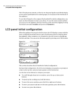
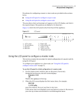
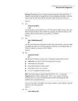
Initializing Symantec Network Security 73 LCD panel initial configuration For more information about master and slave nodes, see the Symantec Network Security Administration Guide. If you wish to configure your appliance as a master node, see "Using the LCD panel to configure a master node" on page 69. To use the LCD panel for initial configuration of a slave node 1 Use the master power switch to turn on the power, if necessary. During the boot process, the LCD screen displays: Symantec v1.03 OK Wait for the appliance to boot up. 2 When the LCD screen displays the first menu choice, for example: SNS7120 1. LCD Config press the e button. Press s at any time to start over. If this menu item is not displayed, press any button to return to the menu, or press the up or down arrow buttons to scroll through the menu. 3 For: Local IP Address [000]000.000.000 use the arrow buttons to enter the local IP address for the appliance. Use the up or down buttons to scroll through the numbers for each three-digit part of the address. Use the right or left buttons to move the cursor brackets. Note: If this node is not behind a NAT router, this is the address the master node will use to communicate with this slave node. Otherwise, the master uses the NAT address that is provided later in the procedure. Press e. 4 For: Local IP Netmask [000]000.000.000 use the arrow buttons to enter the netmask for the local subnet, for example: 255.255.255.000. The netmask designates the part of the address that refers to the network, as opposed to the host. Press e. 5 For: Default Gateway [000]000.000.000
-
 1
1 -
2
-
3
-
4
-
5
-
6
-
7
-
8
-
9
-
10
-
11
-
12
-
13
-
14
-
15
-
16
-
17
-
18
-
19
-
20
-
21
-
22
-
23
-
24
-
25
-
26
-
27
-
28
-
29
-
30
-
31
-
32
-
33
-
34
-
35
-
36
-
37
-
38
-
39
-
40
-
41
-
42
-
43
-
44
-
45
-
46
-
47
-
48
-
49
-
50
-
51
-
52
-
53
-
54
-
55
-
56
-
57
-
58
-
59
-
60
-
61
-
62
-
63
-
64
-
65
-
66
-
67
-
68
-
69
-
70
-
71
-
72
-
73
-
74
-
75
-
 76
76 -
 77
77 -
 78
78 -
 79
79 -
 80
80 -
 81
81 -
 82
82 -
 83
83 -
 84
84 -
 85
85 -
 86
86 -
87
-
88
-
89
-
90
-
91
-
92
-
93
-
94
-
95
-
96
-
97
-
98
-
99
-
100
-
101
-
102
-
103
-
104
-
105
-
106
-
107
-
108
-
109
-
110
-
111
-
112
-
113
-
114
-
115
-
116
-
117
-
118
-
119
-
120
-
121
-
122
-
123
-
124
-
125
-
126
-
127
-
128
-
129
-
130
-
131
-
132
-
133
-
134
-
135
-
136
-
137
-
138
-
139
-
140
-
141
-
142
-
143
-
144
-
145
-
146
-
147
-
148
-
149
-
150
-
151
-
152
-
153
-
154
-
155
-
156
-
157
-
158
-
159
-
160
-
161
-
162
-
163
-
164
-
165
-
166
-
167
-
168
-
169
-
170
-
171
-
172
-
173
-
174
-
175
-
176
-
177
-
178
-
179
-
180
-
181
-
182
-
183
-
184
-
185
-
186
-
187
-
188
-
189
-
190
-
191
-
192
-
193
-
194
-
195
-
196
-
197
-
198
-
199
-
200
-
201
-
202
-
203
-
204
-
205
-
206
-
207
-
208
-
209
-
210
-
211
-
212
-
213
-
214
 |
 |
