Symantec 10521148 Implementation Guide - Page 49
Clustering, Table 3-5, LED label, LED name, Description
 |
View all Symantec 10521148 manuals
Add to My Manuals
Save this manual to your list of manuals |
Page 49 highlights
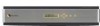
Figure 3-7 Bypass unit rear panel LEDs Deploying the 7100 Series 41 Deployment options Clustering Table 3-5 describes the LEDs shown in the diagram. Table 3-5 Bypass unit rear panel LED descriptions LED label LED name Description LT ALM BYP ON GIG Link test Alarm Bypass Online Gigabit The LT LED glows green to indicate an active link signal on the port. The ALM LED in the top right corner of the Net A port glows red for an alarm condition such as lack of a link signal on one or more ports in the port group. The BYP LED in the top right corner of the App A port glows yellow when the port group is operating in bypass mode. The ON LED in the top right corner of the App B port glows green when the port group is operating in online mode. The GIG LED in the top right corner of the Net B port glows green when the port group is operating in gigabit mode (1000Mbps). It is off when the port group is operating at 100 Mbps or 10 Mbps). You can combine the Symantec Network Security 7100 Series appliance with other nodes and appliances into a cluster. One node within the cluster functions as the master node, and the others act as slaves. You can access and configure all nodes in the cluster from the same Network Security console. You can configure cluster parameters on the master node, which then propagate to the slave nodes. This is discussed in more detail in the Symantec Network Security Administration Guide.
-
 1
1 -
2
-
3
-
4
-
5
-
6
-
7
-
8
-
9
-
10
-
11
-
12
-
13
-
14
-
15
-
16
-
17
-
18
-
19
-
20
-
21
-
22
-
23
-
24
-
25
-
26
-
27
-
28
-
29
-
30
-
31
-
32
-
33
-
34
-
35
-
36
-
37
-
38
-
39
-
40
-
41
-
42
-
43
-
 44
44 -
 45
45 -
 46
46 -
 47
47 -
 48
48 -
 49
49 -
 50
50 -
 51
51 -
 52
52 -
 53
53 -
 54
54 -
55
-
56
-
57
-
58
-
59
-
60
-
61
-
62
-
63
-
64
-
65
-
66
-
67
-
68
-
69
-
70
-
71
-
72
-
73
-
74
-
75
-
76
-
77
-
78
-
79
-
80
-
81
-
82
-
83
-
84
-
85
-
86
-
87
-
88
-
89
-
90
-
91
-
92
-
93
-
94
-
95
-
96
-
97
-
98
-
99
-
100
-
101
-
102
-
103
-
104
-
105
-
106
-
107
-
108
-
109
-
110
-
111
-
112
-
113
-
114
-
115
-
116
-
117
-
118
-
119
-
120
-
121
-
122
-
123
-
124
-
125
-
126
-
127
-
128
-
129
-
130
-
131
-
132
-
133
-
134
-
135
-
136
-
137
-
138
-
139
-
140
-
141
-
142
-
143
-
144
-
145
-
146
-
147
-
148
-
149
-
150
-
151
-
152
-
153
-
154
-
155
-
156
-
157
-
158
-
159
-
160
-
161
-
162
-
163
-
164
-
165
-
166
-
167
-
168
-
169
-
170
-
171
-
172
-
173
-
174
-
175
-
176
-
177
-
178
-
179
-
180
-
181
-
182
-
183
-
184
-
185
-
186
-
187
-
188
-
189
-
190
-
191
-
192
-
193
-
194
-
195
-
196
-
197
-
198
-
199
-
200
-
201
-
202
-
203
-
204
-
205
-
206
-
207
-
208
-
209
-
210
-
211
-
212
-
213
-
214
 |
 |
