Symantec 10521148 Implementation Guide - Page 72
Cabling for passive mode monitoring
 |
View all Symantec 10521148 manuals
Add to My Manuals
Save this manual to your list of manuals |
Page 72 highlights
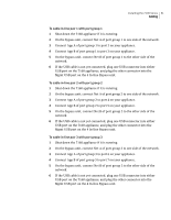
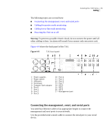
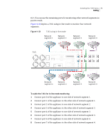
64 Installing the 7100 Series Cabling To connect the management port ◆ Connect the management port (port 11) on the appliance to your management network. To connect the reset ports 1 Connect the first reset port (port 8) on the appliance to a monitored network where you want to send TCP resets. 2 Connect the second reset port (port 9) on the appliance to a monitored network where you want to send TCP resets. 3 Connect the third reset port (port 10) on the appliance to a monitored network where you want to send TCP resets. To connect the serial port ◆ Connect the serial port on the appliance to a laptop, PC, or other serial device. Cabling for passive mode monitoring The 7161 appliance can monitor up to eight separate network segments. Four of the 7161 monitoring ports are 1000 Base-SX optical fiber ports, and four are 10/100/1000 Base-T Ethernet ports. Use multimode fiber cables with LC fiber optic connectors for the 7161 fiber ports, and Ethernet cables with RJ45 connectors for the copper ports. To access network segments for monitoring, you can connect each port to a hub, a router, or a switch. To cable the 7161 for passive mode monitoring ◆ Connect ports 0 through 7 of the appliance to the eight network segments that you want to monitor. Cabling for in-line mode monitoring The 7161 appliance provides in-line mode monitoring for up to four network segments. In-line mode requires an interface pair for each monitored network segment. The interface pair can be ports 0 and 1, ports 2 and 3, ports 4 and 5, or ports 6 and 7. Other port combinations are not supported. Within each interface pair, the lower numbered port (the top port on the NIC) connects to one side of the network, while the port with the higher number connects to the other side of the network. To use in-line mode for monitoring fewer than four network segments, you may use any of the supported interface pairs (ports 0/1, ports 2/3, ports 4/5, or ports
-
 1
1 -
2
-
3
-
4
-
5
-
6
-
7
-
8
-
9
-
10
-
11
-
12
-
13
-
14
-
15
-
16
-
17
-
18
-
19
-
20
-
21
-
22
-
23
-
24
-
25
-
26
-
27
-
28
-
29
-
30
-
31
-
32
-
33
-
34
-
35
-
36
-
37
-
38
-
39
-
40
-
41
-
42
-
43
-
44
-
45
-
46
-
47
-
48
-
49
-
50
-
51
-
52
-
53
-
54
-
55
-
56
-
57
-
58
-
59
-
60
-
61
-
62
-
63
-
64
-
65
-
66
-
 67
67 -
 68
68 -
 69
69 -
 70
70 -
 71
71 -
 72
72 -
 73
73 -
 74
74 -
 75
75 -
 76
76 -
 77
77 -
78
-
79
-
80
-
81
-
82
-
83
-
84
-
85
-
86
-
87
-
88
-
89
-
90
-
91
-
92
-
93
-
94
-
95
-
96
-
97
-
98
-
99
-
100
-
101
-
102
-
103
-
104
-
105
-
106
-
107
-
108
-
109
-
110
-
111
-
112
-
113
-
114
-
115
-
116
-
117
-
118
-
119
-
120
-
121
-
122
-
123
-
124
-
125
-
126
-
127
-
128
-
129
-
130
-
131
-
132
-
133
-
134
-
135
-
136
-
137
-
138
-
139
-
140
-
141
-
142
-
143
-
144
-
145
-
146
-
147
-
148
-
149
-
150
-
151
-
152
-
153
-
154
-
155
-
156
-
157
-
158
-
159
-
160
-
161
-
162
-
163
-
164
-
165
-
166
-
167
-
168
-
169
-
170
-
171
-
172
-
173
-
174
-
175
-
176
-
177
-
178
-
179
-
180
-
181
-
182
-
183
-
184
-
185
-
186
-
187
-
188
-
189
-
190
-
191
-
192
-
193
-
194
-
195
-
196
-
197
-
198
-
199
-
200
-
201
-
202
-
203
-
204
-
205
-
206
-
207
-
208
-
209
-
210
-
211
-
212
-
213
-
214
 |
 |
