Panasonic WJHD316A WJHD309A User Guide - Page 106
Time & Date] Setting of the date and time, Summer Time Day Light Savings Table
 |
View all Panasonic WJHD316A manuals
Add to My Manuals
Save this manual to your list of manuals |
Page 106 highlights
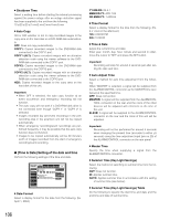
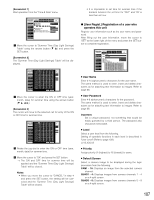
8 Shutdown Time Select a waiting time before starting the internal processing against the power outage after an outage detection signal has been supplied to the unit from the following. 10 s/20 s/30 s/1 min/2 min/3 min/4 min/5 min 8 Auto Copy ON or OFF whether or not to copy recorded images to the copy area on the hard disk or a DVD-RAM disk automatically. OFF: Does not copy automatically. COPY1: Copies recorded images to the DVD-RAM disk connected to the COPY1 port. COPY1 (ALT): Copies recorded images with an alteration detection code using the viewer software to the DVDRAM disk connected to the COPY1 port. COPY2: Copies recorded images to the DVD-RAM disk connected to the COPY2 port. COPY2 (ALT): Copies recorded images with an alteration detection code using the viewer software to the DVDRAM disk connected to the COPY2 port. HDD: Copies recorded images to the copy area on the hard disk of this unit. Important: • When OFF is selected, the auto copy function at an event occurrence and emergency recording will not function. • The auto copy will not work if a DVD-RAM disk drive is not connected even though "COPY 1" or "COPY 2" is selected. • Images recorded (by pre-event recording) in the prerecording area in the extension unit will not be copied automatically. • When emergency recording/event recordings are performed frequently, it may be possible that the auto copy function does not function. • Images to be copied automatically will be 30 minute's worth of images recorded from the start of emergency recording/event recording. G [Time & Date] Setting of the date and time Perform the following settings of the time and date. SETUP MENU Advanced System Switcher Recording Display Event Comm Schedule Maintenance LIVE Basic Setup Time & Date User Regist. User Edit User Delete Host Regist. Host Edit Host Delete User Level Save/Load Quick Menu I Date Format MMM.DD.YY I Time Format 12H I Time & Date JAN . 01 . 04 12 : 00 : 00 AM SET I Auto Adjust Time Master Time I Summer Time(Day Light Savings) OFF 12 :00 AM AUTO I Summer Time(Day Light Savings)Table SETUP 8 Date Format Select a display format for the date from the following. (Ex. April 1, 2004) YY.MM.DD: 04.4.1 MMM.DD.YY: APR.1.04 DD.MMM.YY: 1.APR.04 8 Time Format Select a display format for the time from the following. (Ex. 3 o' clock in the afternoon) 12h: 3:00:00 PM 24h: 15:00:00 8 Time & Date Adjust the current time and date. Enter year, month, day, hour, minute and second in order, move the cursor to "SET" and press the SET button. Important: Recording will stop for around 4 seconds just after setting the date and time. 8 Auto Adjust Time Select a method for auto time adjustment from the following. When "MASTER" is selected, a signal will be supplied from the ALARM/CONTROL connector as the MASTER time (see below) at the specified time. OFF: Does not function. MASTER: A signal will be supplied from the ALARM/CON- TROL connector on the rear and the clock of the other devices will be adjusted with reference to the time of this unit. SLAVE: A signal will be supplied to the ALARM/CONTROL connector on the rear and the clock of this unit will be adjusted. Important: Recording will not be performed for around 4 seconds when changing the present time (accurate to within ±5 seconds) using the time adjustment input (pin no.20) of the ALARM/CONTROL connector on the rear panel. 8 Master Time Specify the time when supplying a signal from the ALARM/CONTROL connector. 8 Summer Time (Day Light Savings) Select the method of switching to summer time from the following. OUT: Does not function. IN: Applies summer time. AUTO: Applies summer time in accordance with the setting of summer time (see below). 8 Summer Time (Day Light Savings) Table Do the following to specify the start time and date and the end time and date of summer time. 106
-
 1
1 -
2
-
3
-
4
-
5
-
6
-
7
-
8
-
9
-
10
-
11
-
12
-
13
-
14
-
15
-
16
-
17
-
18
-
19
-
20
-
21
-
22
-
23
-
24
-
25
-
26
-
27
-
28
-
29
-
30
-
31
-
32
-
33
-
34
-
35
-
36
-
37
-
38
-
39
-
40
-
41
-
42
-
43
-
44
-
45
-
46
-
47
-
48
-
49
-
50
-
51
-
52
-
53
-
54
-
55
-
56
-
57
-
58
-
59
-
60
-
61
-
62
-
63
-
64
-
65
-
66
-
67
-
68
-
69
-
70
-
71
-
72
-
73
-
74
-
75
-
76
-
77
-
78
-
79
-
80
-
81
-
82
-
83
-
84
-
85
-
86
-
87
-
88
-
89
-
90
-
91
-
92
-
93
-
94
-
95
-
96
-
97
-
98
-
99
-
100
-
 101
101 -
 102
102 -
 103
103 -
 104
104 -
 105
105 -
 106
106 -
 107
107 -
 108
108 -
 109
109 -
 110
110 -
 111
111 -
112
-
113
-
114
-
115
-
116
-
117
-
118
-
119
-
120
-
121
-
122
-
123
-
124
-
125
-
126
-
127
-
128
-
129
-
130
-
131
-
132
-
133
-
134
-
135
-
136
-
137
-
138
-
139
-
140
-
141
-
142
-
143
-
144
-
145
-
146
-
147
-
148
-
149
-
150
-
151
-
152
-
153
-
154
-
155
-
156
-
157
-
158
-
159
-
160
-
161
-
162
-
163
-
164
-
165
-
166
-
167
-
168
-
169
-
170
-
171
-
172
-
173
-
174
-
175
-
176
-
177
-
178
-
179
-
180
-
181
-
182
 |
 |
