Panasonic WJHD316A WJHD309A User Guide - Page 85
Mode Switch, RS485 Port, When connecting a system device and this unit is installed
 |
View all Panasonic WJHD316A manuals
Add to My Manuals
Save this manual to your list of manuals |
Page 85 highlights
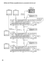
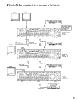
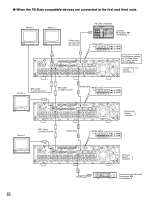
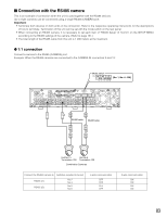
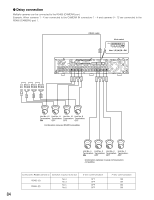
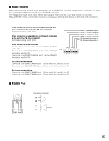
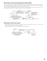
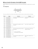
I Mode Switch RS485 interface is used to communicate between this unit and the PS·Data compatible system device. In this case, it is necessary to terminate both devices on both ends of the RS485 connection. The settings of the mode switch will be different depending on whether this unit is used as a receiver or a controller. When an RS 485 camera is connected to this unit, it is necessary to terminate both devices on both ends of the connection. • When connecting this unit with the system controller and this is installed at the end of the PS·Data connection PS·Data termination switch 1: ON • When connecting a system device and this unit is installed at the end of the PS·Data connection PS·Data terminating switch 2: ON RS485 (1) terminating switch RS485 (1) 2/4-wire changeover RS485 (2) terminating switch RS485 (2) 2/4-wire changeover PS•Data terminating switch 1 PS•Data terminating switch 2 • When connecting RS485 cameras Set the termination switch of the connected RS485 (CAMERA) port to ON. ON Connected to the RS485 (CAMERA) port 1: Set the RS485 (1) termination switch to ON. Connected to the RS485 (CAMERA) port 2: Set the RS485 (2) termination switch to ON. 12345678 • For 2-wire communication Connected to the RS485 (CAMERA) port 1: Set the switch No.2 and No.3 to ON. Connected to the RS485 (CAMERA) port 2: Set the switch No.5 and No.6 to ON. • For 4-wire communication Connected to the RS485 (CAMERA) port 1: Set the switch No.2 and No.3 to OFF. Connected to the RS485 (CAMERA) port 2: Set the switch No.5 and No.6 to OFF. I RS485 Port DATA G TA TB RA RB G N N D Output Input D Internal block diagram RA RB TA TB 85
-
 1
1 -
2
-
3
-
4
-
5
-
6
-
7
-
8
-
9
-
10
-
11
-
12
-
13
-
14
-
15
-
16
-
17
-
18
-
19
-
20
-
21
-
22
-
23
-
24
-
25
-
26
-
27
-
28
-
29
-
30
-
31
-
32
-
33
-
34
-
35
-
36
-
37
-
38
-
39
-
40
-
41
-
42
-
43
-
44
-
45
-
46
-
47
-
48
-
49
-
50
-
51
-
52
-
53
-
54
-
55
-
56
-
57
-
58
-
59
-
60
-
61
-
62
-
63
-
64
-
65
-
66
-
67
-
68
-
69
-
70
-
71
-
72
-
73
-
74
-
75
-
76
-
77
-
78
-
79
-
 80
80 -
 81
81 -
 82
82 -
 83
83 -
 84
84 -
 85
85 -
 86
86 -
 87
87 -
 88
88 -
 89
89 -
 90
90 -
91
-
92
-
93
-
94
-
95
-
96
-
97
-
98
-
99
-
100
-
101
-
102
-
103
-
104
-
105
-
106
-
107
-
108
-
109
-
110
-
111
-
112
-
113
-
114
-
115
-
116
-
117
-
118
-
119
-
120
-
121
-
122
-
123
-
124
-
125
-
126
-
127
-
128
-
129
-
130
-
131
-
132
-
133
-
134
-
135
-
136
-
137
-
138
-
139
-
140
-
141
-
142
-
143
-
144
-
145
-
146
-
147
-
148
-
149
-
150
-
151
-
152
-
153
-
154
-
155
-
156
-
157
-
158
-
159
-
160
-
161
-
162
-
163
-
164
-
165
-
166
-
167
-
168
-
169
-
170
-
171
-
172
-
173
-
174
-
175
-
176
-
177
-
178
-
179
-
180
-
181
-
182
 |
 |
