Panasonic WJHD316A WJHD309A User Guide - Page 91
Alarm connection, Terminal, Active time
 |
View all Panasonic WJHD316A manuals
Add to My Manuals
Save this manual to your list of manuals |
Page 91 highlights
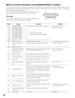
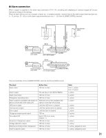
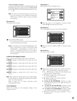
G Alarm connection When a signal is supplied to the alarm input terminals of CH 1-16, recording and displaying of camera images will be performed according to the settings. When an alarm device such as a buzzer, a lamp, etc., is installed outside, connect them to the alarm output terminals (pin nos. 9 - 12, pin nos. 23 - 25) or to the alarm output terminals (pin nos. 1 - 9) of the ALARM/CONTROL terminal. Sensor Security door switch (Ch 16 alarm input) (GND) (Ch 1 alarm input) Alarming devices (Earth) !3 o !4 q Relay, etc. Install according to your needs. (Ch 1 alarm output) @2 ALARM Alarming devices (Earth) !3 o Relay, etc. Install according to your needs. (Ch 16 alarm output) ALARM/CONTROL Time and polarities of the ALARM/CONTROL terminal and the ALARM terminal Terminal Alarm input Active time 100 ms or more Alarm output The set time on the SETUP MENU Alarm reset input 100 ms or more Emergency recording input 100 ms or more Alarm output for available disk space of While the size of the available disk device connected to the copy port space is less than the set size HDD error output Until the HDD error is cleared Camera error output Until the camera error is cleared Error output Until the error is cleared Outage processing end output 100 ms Time adjust I/O Input: 100 ms or more Output: 1 s Sequence changeover output 100 ms or more Outage detection output 100 ms or more External recording mode changeover 100 ms or more Alarm suspend output 100 ms or more Note N.O.: L active N.C.: H active L active L active L active L active L active L active L active H active L active L active L active L active, judged by level L active, judged by level 91
-
 1
1 -
2
-
3
-
4
-
5
-
6
-
7
-
8
-
9
-
10
-
11
-
12
-
13
-
14
-
15
-
16
-
17
-
18
-
19
-
20
-
21
-
22
-
23
-
24
-
25
-
26
-
27
-
28
-
29
-
30
-
31
-
32
-
33
-
34
-
35
-
36
-
37
-
38
-
39
-
40
-
41
-
42
-
43
-
44
-
45
-
46
-
47
-
48
-
49
-
50
-
51
-
52
-
53
-
54
-
55
-
56
-
57
-
58
-
59
-
60
-
61
-
62
-
63
-
64
-
65
-
66
-
67
-
68
-
69
-
70
-
71
-
72
-
73
-
74
-
75
-
76
-
77
-
78
-
79
-
80
-
81
-
82
-
83
-
84
-
85
-
 86
86 -
 87
87 -
 88
88 -
 89
89 -
 90
90 -
 91
91 -
 92
92 -
 93
93 -
 94
94 -
 95
95 -
 96
96 -
97
-
98
-
99
-
100
-
101
-
102
-
103
-
104
-
105
-
106
-
107
-
108
-
109
-
110
-
111
-
112
-
113
-
114
-
115
-
116
-
117
-
118
-
119
-
120
-
121
-
122
-
123
-
124
-
125
-
126
-
127
-
128
-
129
-
130
-
131
-
132
-
133
-
134
-
135
-
136
-
137
-
138
-
139
-
140
-
141
-
142
-
143
-
144
-
145
-
146
-
147
-
148
-
149
-
150
-
151
-
152
-
153
-
154
-
155
-
156
-
157
-
158
-
159
-
160
-
161
-
162
-
163
-
164
-
165
-
166
-
167
-
168
-
169
-
170
-
171
-
172
-
173
-
174
-
175
-
176
-
177
-
178
-
179
-
180
-
181
-
182
 |
 |
