Panasonic WJHD316A WJHD309A User Guide - Page 12
On Monitor 1, Signal Ground Terminal SIGNAL GND - wj hd316a setup
 |
View all Panasonic WJHD316A manuals
Add to My Manuals
Save this manual to your list of manuals |
Page 12 highlights
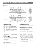
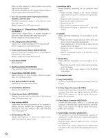
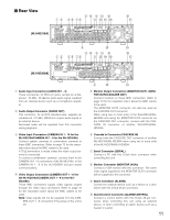
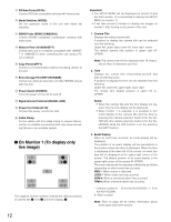
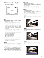
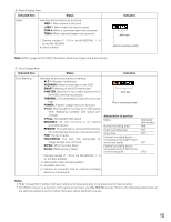
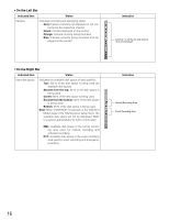
!1 PS·Data Ports (DATA) Connect PS·Data compatible devices with these ports. !2 Mode Switches (MODE) Set the operation mode of this unit with these dip switches. !3 RS485 Ports (RS485 (CAMERA)) Connect RS485 compatible combination cameras with these ports. !4 Network Port (10/100BASE-T) Connect this unit to a network compatible with 10BASET or 100BASE-Tx when controlling this unit using a PC via a network. !5 Copy Port (COPY1) Connect a recommended external recording device to this port. !6 Extra Storage Port (EXT STORAGE) Connect an optional extension unit (WJ-HDE300 series) with this port. !7 Power Switch (POWER) Turns the power of this unit on and off. !8 Signal Ground Terminal (SIGNAL GND) !9 Power Cord Inlet (AC IN) Connect the power cord to this inlet. @0 Cable Clamp Fix the cables with this cable clamp to prevent disconnection or unstable connections that may cause recording failures or an unstable system. I On Monitor 1 (To display only live image) q we q we q q we q we The negative circled numbers indicate the default positions of camera title q, time w and event display e. Important: • The SETUP MENU will be displayed on monitor 2 and the VGA monitor. (It is impossible to display the SETUP MENU on monitor 1.) • It will take around 2 minutes to display live images on monitor 1 after turning on the power of the unit. 1. Camera Title Displays the edited camera title. A position to display the camera title can be selected from the following. Upper left, upper right, lower left, lower right, center The default camera title position is upper right (RUPPER). Note: The camera title will be displayed with 16 characters (2 lines: 8 characters per line). 2. Time Displays the current time (hour:minute:second) and date (month:day:year). A position to display the time can be selected from the following. Upper left, lower left, upper right, lower right The default time display position is upper left (LUPPER). Notes: • When the camera title and the time display are layered, only the time display will be displayed. • When monitor 1 is selected, it is possible to turn on/off display of the camera title and the time by pressing the camera selection button 8 for the WJHD316A (the camera selection button 6 for the WJHD309A) while the shift function is on (by pressing the SHIFT button). 3. Event Display When an event has occurred, an event display will be displayed. The position of an event display will be symmetrical to the position where the time is displayed. When the time is displayed at the lower left of the screen, an event display will be displayed at the upper right corner of the screen. The default position of an event display is the upper right corner of the screen (R-UPPER). The event display will be displayed differently as follows depending on which event has occurred. VMD-*: When motion is detected. LOSS-*: When video loss has occurred. COM-#: When a command alarm has occurred. TRM-#: When a terminal alarm has occurred. *: Camera number (1 - 16 for the WJ-HD316A, 1 - 9 for the WJ-HD309A) #: Alarm number Note: Refer to page 49 for further information about event types and event actions. 12
-
 1
1 -
2
-
3
-
4
-
5
-
6
-
 7
7 -
 8
8 -
 9
9 -
 10
10 -
 11
11 -
 12
12 -
 13
13 -
 14
14 -
 15
15 -
 16
16 -
 17
17 -
18
-
19
-
20
-
21
-
22
-
23
-
24
-
25
-
26
-
27
-
28
-
29
-
30
-
31
-
32
-
33
-
34
-
35
-
36
-
37
-
38
-
39
-
40
-
41
-
42
-
43
-
44
-
45
-
46
-
47
-
48
-
49
-
50
-
51
-
52
-
53
-
54
-
55
-
56
-
57
-
58
-
59
-
60
-
61
-
62
-
63
-
64
-
65
-
66
-
67
-
68
-
69
-
70
-
71
-
72
-
73
-
74
-
75
-
76
-
77
-
78
-
79
-
80
-
81
-
82
-
83
-
84
-
85
-
86
-
87
-
88
-
89
-
90
-
91
-
92
-
93
-
94
-
95
-
96
-
97
-
98
-
99
-
100
-
101
-
102
-
103
-
104
-
105
-
106
-
107
-
108
-
109
-
110
-
111
-
112
-
113
-
114
-
115
-
116
-
117
-
118
-
119
-
120
-
121
-
122
-
123
-
124
-
125
-
126
-
127
-
128
-
129
-
130
-
131
-
132
-
133
-
134
-
135
-
136
-
137
-
138
-
139
-
140
-
141
-
142
-
143
-
144
-
145
-
146
-
147
-
148
-
149
-
150
-
151
-
152
-
153
-
154
-
155
-
156
-
157
-
158
-
159
-
160
-
161
-
162
-
163
-
164
-
165
-
166
-
167
-
168
-
169
-
170
-
171
-
172
-
173
-
174
-
175
-
176
-
177
-
178
-
179
-
180
-
181
-
182
 |
 |
