Panasonic WJHD316A WJHD309A User Guide - Page 131
RS485 Setup] Settings for RS485, Baud Rate, Data Bit, Parity, Stop Bit, Retry Timing, Alarm Data
 |
View all Panasonic WJHD316A manuals
Add to My Manuals
Save this manual to your list of manuals |
Page 131 highlights
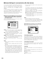
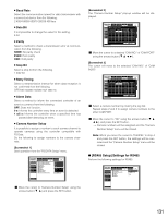
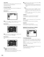
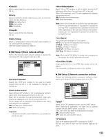
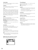
8 Baud Rate Select the communication speed for data transmission with a connected device from the following. 2 400/4 800/9 600/19 200/38 400 bps 8 Data Bit It is impossible to change the value for this setting. 8 bit 8 Parity Select a method to check a transmission error at communication from the following. NONE: No parity check EVEN: Even parity ODD: Odd parity 8 Stop Bit Select a stop bit from the following. 1 bit/2 bit 8 Retry Timing Select a retransmission interval for when data reception is not confirmed from the following. OFF/100 ms/200 ms/400 ms/1 000 ms 8 Alarm Data Select a method to inform the connected controller of an event occurrence from the following. OFF: Does not function. 0 s: Informs the controller every time an event is detected. 1 s/5 s: Informs the controller when a specified time has passed after detecting an event. 8 Camera Number Setup It is possible to assign a number to each camera channel to operate cameras using the controller compatible with PS·Data. Do the following to assign numbers to the camera channels. [Screenshot 1] Start operation from the "PS·DATA Setup" menu. SETUP MENU Advanced Camera Control PS.DATA Setup RS485 Setup RS232C Setup NW Setup 1 NW Setup 2 NTP Setup System Switcher Recording Display Event Comm I Unit Address(System) I Unit Address(Controller) I Cascade I Baud Rate I Data Bit I Parity I Stop Bit I Retry Timing I Alarm Data I Camera Number Setup Schedule Maintenance LIVE 001 001 OFF 9600 8 NONE 1 OFF 1s SETUP Quick Menu z Move the cursor to "Camera Number Setup" using the arrows button (C D) and press the SET button. [Screenshot 2] The "Camera Number Setup" pop-up window will be displayed. SETUP MENU Advanced System Switcher Recording Display Event Comm Schedule Maintenance LIVE I Camera Control CamIeraUNniut mAbderersSse(Stuypstem) PS.DATA SetupCAM RS485 Setup 1PIIIORUCBTnaasuitcdAaRddCareeAtes0Ms0(1NCOon. trollCerA)M PORT 9 RS232C Setup 2I Data Bit 002 10 NW Setup 1 3I Parity 003 4I Stop Bit 004 11 12 NW Setup 2 NTP Setup 5I Retry Timi0n0g5 13 67II AClaamrmerDa aNt0ua0m6ber Setup 007 14 15 8 008 16 001 0O0FC1F AM NO. 9600 009 8 010 NONE011 1 012 OFF 013 1s S0ET1U4P 015 016 Quick Menu O K CANCEL x Move the cursor to a desired "CAM NO." of "CAM PORT" using the arrows button (C D A B). [Screenshot 3] The cursor will move to the selected "CAM NO." of "CAM PORT". SETUP MENU Advanced System Switcher Recording Display Event Comm Schedule Maintenance LIVE I Camera Control CamIeraUNniut mAbderersSse(Stuypstem) PS.DATA SetupCAM PIIORUCTnasitcAaddCreeAsMs(NCOon. trollCerA)M PORT RS485 Setup 1I Baud Rate001 9 RS232C Setup 2I Data Bit 002 10 NW Setup 1 3I Parity 003 11 4I Stop Bit 004 12 NW Setup 2 NTP Setup 5I Retry Timi0n0g5 13 67II AClaamrmerDa aNt0ua0m6ber Setup 007 14 15 8 008 16 001 001 OFCF AM NO. 9600 009 8 010 NONE011 1 012 OFF 013 1s S0ET1U4P 015 016 Quick Menu O K CANCEL c Select a camera number by rotating the jog dial. Repeat steps 2 and 3 to assign camera numbers to the other CAM PORT. v Move the cursor to "OK" using the arrows button (C D A B), and press the SET button. → Camera numbers will be assigned and the "Camera Number Setup" menu will be closed. Note: When you move the cursor to "CANCEL" in step 4 and press the SET button, the settings will be canceled and the "Camera Number Setup" menu will be closed. G [RS485 Setup] Settings for RS485 Perform the following settings for RS485. SETUP MENU Advanced Camera Control PS.DATA Setup RS485 Setup RS232C Setup NW Setup 1 NW Setup 2 NTP Setup System Switcher Recording Display Event Comm I Baud Rate I Control Camera CH I Data Bit I Parity I Stop Bit Schedule Maintenance 19200 SETUP 8 NONE 1 LIVE Quick Menu 131
-
 1
1 -
2
-
3
-
4
-
5
-
6
-
7
-
8
-
9
-
10
-
11
-
12
-
13
-
14
-
15
-
16
-
17
-
18
-
19
-
20
-
21
-
22
-
23
-
24
-
25
-
26
-
27
-
28
-
29
-
30
-
31
-
32
-
33
-
34
-
35
-
36
-
37
-
38
-
39
-
40
-
41
-
42
-
43
-
44
-
45
-
46
-
47
-
48
-
49
-
50
-
51
-
52
-
53
-
54
-
55
-
56
-
57
-
58
-
59
-
60
-
61
-
62
-
63
-
64
-
65
-
66
-
67
-
68
-
69
-
70
-
71
-
72
-
73
-
74
-
75
-
76
-
77
-
78
-
79
-
80
-
81
-
82
-
83
-
84
-
85
-
86
-
87
-
88
-
89
-
90
-
91
-
92
-
93
-
94
-
95
-
96
-
97
-
98
-
99
-
100
-
101
-
102
-
103
-
104
-
105
-
106
-
107
-
108
-
109
-
110
-
111
-
112
-
113
-
114
-
115
-
116
-
117
-
118
-
119
-
120
-
121
-
122
-
123
-
124
-
125
-
 126
126 -
 127
127 -
 128
128 -
 129
129 -
 130
130 -
 131
131 -
 132
132 -
 133
133 -
 134
134 -
 135
135 -
 136
136 -
137
-
138
-
139
-
140
-
141
-
142
-
143
-
144
-
145
-
146
-
147
-
148
-
149
-
150
-
151
-
152
-
153
-
154
-
155
-
156
-
157
-
158
-
159
-
160
-
161
-
162
-
163
-
164
-
165
-
166
-
167
-
168
-
169
-
170
-
171
-
172
-
173
-
174
-
175
-
176
-
177
-
178
-
179
-
180
-
181
-
182
 |
 |
