Panasonic WJHD316A WJHD309A User Guide - Page 90
How to Use the Terminals of the ALARM Connector, Pin Configuration
 |
View all Panasonic WJHD316A manuals
Add to My Manuals
Save this manual to your list of manuals |
Page 90 highlights
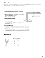
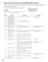
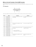
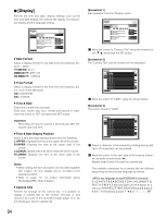
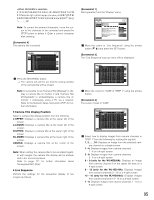
I How to Use the Terminals of the ALARM Connector These terminals are used to connect the alarm devices, such as sensors, door switches, etc. The pin configurations of these terminals are as shown below. The connector used should be compatible with the pin configuration. Pin Configuration !3 q ALARM @5 !4 The pin array is different from other disk recorders. Make sure that the connection is correct by referring to the following. Pin No. q w e r t y u i o !0 !1 !2 !3, !4 !5 !6 !7 !8 !9 @0 @1 @2 @3 @4 @5 Signal Ch 1 alarm input Ch 2 alarm input Ch 3 alarm input Ch 4 alarm input Ch 5 alarm input Ch 6 alarm input Ch 7 alarm input Ch 8 alarm input Ch 1 alarm output Ch 2 alarm output Ch 3 alarm output Ch 4 alarm output Earth (Grounding) Ch 9 alarm input Ch 10 alarm input Ch 11 alarm input Ch 12 alarm input Ch 13 alarm input Ch 14 alarm input Ch 15 alarm input Ch 16 alarm input Ch 5 alarm output Ch 6 alarm output Ch 7 alarm output Operation Event action will be performed according to the settings. Remarks Non-voltage make contact/-100 mA, 5 V pull-up Alarm signal will be supplied at an event occurrence Open collector output/24 V, 100 mA Event action will be performed according to the setting. Non-voltage make contact input/ -100 mA, 5 V pull-up Only for the WJ-HD316A (Not available for the WJ-HD309A) Alarm signal will be supplied at an event occurrence Open collector output/24 V max., 100 mA 90
-
 1
1 -
2
-
3
-
4
-
5
-
6
-
7
-
8
-
9
-
10
-
11
-
12
-
13
-
14
-
15
-
16
-
17
-
18
-
19
-
20
-
21
-
22
-
23
-
24
-
25
-
26
-
27
-
28
-
29
-
30
-
31
-
32
-
33
-
34
-
35
-
36
-
37
-
38
-
39
-
40
-
41
-
42
-
43
-
44
-
45
-
46
-
47
-
48
-
49
-
50
-
51
-
52
-
53
-
54
-
55
-
56
-
57
-
58
-
59
-
60
-
61
-
62
-
63
-
64
-
65
-
66
-
67
-
68
-
69
-
70
-
71
-
72
-
73
-
74
-
75
-
76
-
77
-
78
-
79
-
80
-
81
-
82
-
83
-
84
-
 85
85 -
 86
86 -
 87
87 -
 88
88 -
 89
89 -
 90
90 -
 91
91 -
 92
92 -
 93
93 -
 94
94 -
 95
95 -
96
-
97
-
98
-
99
-
100
-
101
-
102
-
103
-
104
-
105
-
106
-
107
-
108
-
109
-
110
-
111
-
112
-
113
-
114
-
115
-
116
-
117
-
118
-
119
-
120
-
121
-
122
-
123
-
124
-
125
-
126
-
127
-
128
-
129
-
130
-
131
-
132
-
133
-
134
-
135
-
136
-
137
-
138
-
139
-
140
-
141
-
142
-
143
-
144
-
145
-
146
-
147
-
148
-
149
-
150
-
151
-
152
-
153
-
154
-
155
-
156
-
157
-
158
-
159
-
160
-
161
-
162
-
163
-
164
-
165
-
166
-
167
-
168
-
169
-
170
-
171
-
172
-
173
-
174
-
175
-
176
-
177
-
178
-
179
-
180
-
181
-
182
 |
 |
