Panasonic WJHD316A WJHD309A User Guide - Page 83
Connection with the RS485 camera, 1 connection
 |
View all Panasonic WJHD316A manuals
Add to My Manuals
Save this manual to your list of manuals |
Page 83 highlights
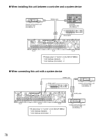
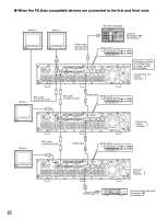
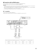
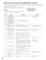
I Connection with the RS485 camera This is an example of connection when the unit is used together with the RS485 devices. Up to eight cameras can be connected using a single RS485 (CAMERA) port. Important: • Terminate both devices on both ends of the connection. Refer to the respective operating instructions for the descriptions of how to terminate. Termination of this unit can be set with the mode switch on the rear panel. • When connecting an RS485 camera, it is necessary to set each item of "RS485 Setup" of "Comm" on the SETUP MENU according to the RS485 settings of the camera. (Refer to page 131.) • The total length of the RS485 cable from this unit is 1 200 meters at the maximum. G 1:1 connection Connect a camera to the RS485 (CAMERA) port. Example: When the RS485 cameras are connected to the CAMERA IN connectors 9 and 13: Mode switch ON 12345678 (No. 1, No. 4 : ON) 3 1 1 SERIAL ALARM 4 2 AUDIO IN AUDIO OUT CASCADE OUT 2 MONITOR OUT CASCADE IN MONITOR (VGA) ALARM/CONTROL 16 15 14 13 12 11 10 9 8 7 IN OUT 16 15 14 13 12 11 10 9 8 7 VIDEO 1 8 MODE 2 1 COPY 1 DATA 6 5 RS485(CAMERA) 10/100BASE-T EXT STORAGE 4 3 2 1 6 5 4 3 2 1 SIGNAL GND POWER AC IN RS485 cable RS485 cable Unit No.13 Unit No.9 Termination: ON Termination: ON Combination Cameras Connect the RS485 camera to Switches required to be set RS485 (1) RS485 (2) No.2 No.3 No.5 No.6 4-wire communication OFF OFF OFF OFF 2-wire communication ON ON ON ON 83
-
 1
1 -
2
-
3
-
4
-
5
-
6
-
7
-
8
-
9
-
10
-
11
-
12
-
13
-
14
-
15
-
16
-
17
-
18
-
19
-
20
-
21
-
22
-
23
-
24
-
25
-
26
-
27
-
28
-
29
-
30
-
31
-
32
-
33
-
34
-
35
-
36
-
37
-
38
-
39
-
40
-
41
-
42
-
43
-
44
-
45
-
46
-
47
-
48
-
49
-
50
-
51
-
52
-
53
-
54
-
55
-
56
-
57
-
58
-
59
-
60
-
61
-
62
-
63
-
64
-
65
-
66
-
67
-
68
-
69
-
70
-
71
-
72
-
73
-
74
-
75
-
76
-
77
-
 78
78 -
 79
79 -
 80
80 -
 81
81 -
 82
82 -
 83
83 -
 84
84 -
 85
85 -
 86
86 -
 87
87 -
 88
88 -
89
-
90
-
91
-
92
-
93
-
94
-
95
-
96
-
97
-
98
-
99
-
100
-
101
-
102
-
103
-
104
-
105
-
106
-
107
-
108
-
109
-
110
-
111
-
112
-
113
-
114
-
115
-
116
-
117
-
118
-
119
-
120
-
121
-
122
-
123
-
124
-
125
-
126
-
127
-
128
-
129
-
130
-
131
-
132
-
133
-
134
-
135
-
136
-
137
-
138
-
139
-
140
-
141
-
142
-
143
-
144
-
145
-
146
-
147
-
148
-
149
-
150
-
151
-
152
-
153
-
154
-
155
-
156
-
157
-
158
-
159
-
160
-
161
-
162
-
163
-
164
-
165
-
166
-
167
-
168
-
169
-
170
-
171
-
172
-
173
-
174
-
175
-
176
-
177
-
178
-
179
-
180
-
181
-
182
 |
 |
