Panasonic WJHD316A WJHD309A User Guide - Page 132
RS232C Setup] Settings for RS232C, Baud Rate, Control Camera CH, Data Bit, Parity, Stop Bit
 |
View all Panasonic WJHD316A manuals
Add to My Manuals
Save this manual to your list of manuals |
Page 132 highlights
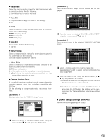
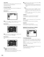
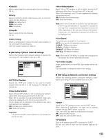
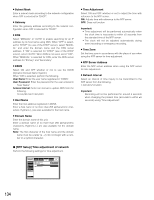
8 Baud Rate Select the communication speed for data transmission with a connected device from the following. 4 800/9 600/19 200 bps 8 Control Camera CH It is possible to assign camera channels to the RS485 ports 1 and 2 as shown below. [Screenshot 1] Start operation from the "RS485 Setup" menu. SETUP MENU Advanced Camera Control PS.DATA Setup RS485 Setup RS232C Setup NW Setup 1 NW Setup 2 NTP Setup System Switcher Recording Display Event Comm I Baud Rate I Control Camera CH I Data Bit I Parity I Stop Bit Schedule Maintenance 19200 SETUP 8 NONE 1 LIVE Quick Menu z Move the cursor to "Control Camera CH" using the arrows button (C D) and press the SET button. [Screenshot 2] The "Control Camera CH" pop-up window will be displayed. SETUP MENU Advanced System Switcher Recording Display Event Comm Schedule Maintenance Camera ConItrol ContIrolBCaaumdeRraatCeH PS.DATA SetupCAMEIRAControl TCEaRmMera CH CAMERA RS485 Setup CAMII1 Data Bit Parity PORT1 CAM9 RS232C Setup CAMI2 Stop BiPt ORT1 CAM10 NW Setup 1 CAM3 CAM4 PORT1 PORT1 CAM11 CAM12 NW Setup 2 CAM5 PORT1 CAM13 NTP Setup CAM6 PORT1 CAM14 CAM7 PORT1 CAM15 CAM8 PORT1 CAM16 19200 SETUP 8 TERM NONPE ORT2 1 PORT2 PORT2 PORT2 PORT2 PORT2 PORT2 PORT2 LIVE Quick Menu O K CANCEL x Move the cursor to a desired cell in the "TERM" column using the arrows button (C D A B). [Screenshot 3] The cursor will move to the selected cell in the "TERM" column. SETUP MENU Advanced System Switcher Recording Display Event Comm Schedule Maintenance Camera ConItrol ContIrolBCaaumdeRraatCeH PS.DATA SetupCAMEIRAControl TCEaRmMera CH CAMERA RS485 Setup CAMII1 Data Bit Parity PORT1 CAM9 RS232C Setup CAMI2 Stop BiPt ORT1 CAM10 NW Setup 1 CAM3 CAM4 PORT1 PORT1 CAM11 CAM12 NW Setup 2 CAM5 PORT1 CAM13 NTP Setup CAM6 PORT1 CAM14 CAM7 PORT1 CAM15 CAM8 PORT1 CAM16 19200 SETUP 8 TERM NONPE ORT2 1 PORT2 PORT2 PORT2 PORT2 PORT2 PORT2 PORT2 LIVE Quick Menu O K CANCEL c Select a port by rotating the jog dial. PORT1: Control through the RS485 port 1. PORT2: Control through the RS485 port 2. Repeat steps 2 and 3 to assign other camera channels to be controlled through the RS485 ports. v Move the cursor to "OK" using the arrows button (C D A B), and press the SET button. → Camera channels and ports to be controlled will be assigned and the "Control Camera CH" menu will be closed. Notes: • When you move the cursor to "CANCEL" in step 4 and press the SET button, the settings will be canceled and the "Control Camera CH" menu will be closed. • The unit number of the camera will be congruent with the camera number. 8 Data Bit The data length for communication will be displayed. It is impossible to change the value for this setting. 8 Parity Methods to check a transmission error at communication will be displayed. It is impossible to change the value for this setting. 8 Stop Bit Number of stop bit will be displayed. It is impossible to change the value for this setting. G [RS232C Setup] Settings for RS232C Perform the following settings for RS232C. SETUP MENU Advanced System Switcher Recording Display Event Comm Camera Control PS.DATA Setup RS485 Setup RS232C Setup NW Setup 1 NW Setup 2 NTP Setup I Unit Address(System) I Baud Rate I Data Bit I Parity I Stop Bit I Retry Timing Schedule Maintenance 001 9600 8 NONE 1 OFF LIVE Quick Menu 8 Unit Address(System) A unit address (System) is a unique number assigned to each system device. The addresses must be unique to identify system devices when connecting multiple system devices. Numbers, "001"-"099", are to be assigned as the unit addresses for the system devices. 8 Baud Rate Select the communication speed for data transmission with a connected device from the following. 9 600/19 200/38 400 bps 132
-
 1
1 -
2
-
3
-
4
-
5
-
6
-
7
-
8
-
9
-
10
-
11
-
12
-
13
-
14
-
15
-
16
-
17
-
18
-
19
-
20
-
21
-
22
-
23
-
24
-
25
-
26
-
27
-
28
-
29
-
30
-
31
-
32
-
33
-
34
-
35
-
36
-
37
-
38
-
39
-
40
-
41
-
42
-
43
-
44
-
45
-
46
-
47
-
48
-
49
-
50
-
51
-
52
-
53
-
54
-
55
-
56
-
57
-
58
-
59
-
60
-
61
-
62
-
63
-
64
-
65
-
66
-
67
-
68
-
69
-
70
-
71
-
72
-
73
-
74
-
75
-
76
-
77
-
78
-
79
-
80
-
81
-
82
-
83
-
84
-
85
-
86
-
87
-
88
-
89
-
90
-
91
-
92
-
93
-
94
-
95
-
96
-
97
-
98
-
99
-
100
-
101
-
102
-
103
-
104
-
105
-
106
-
107
-
108
-
109
-
110
-
111
-
112
-
113
-
114
-
115
-
116
-
117
-
118
-
119
-
120
-
121
-
122
-
123
-
124
-
125
-
126
-
 127
127 -
 128
128 -
 129
129 -
 130
130 -
 131
131 -
 132
132 -
 133
133 -
 134
134 -
 135
135 -
 136
136 -
 137
137 -
138
-
139
-
140
-
141
-
142
-
143
-
144
-
145
-
146
-
147
-
148
-
149
-
150
-
151
-
152
-
153
-
154
-
155
-
156
-
157
-
158
-
159
-
160
-
161
-
162
-
163
-
164
-
165
-
166
-
167
-
168
-
169
-
170
-
171
-
172
-
173
-
174
-
175
-
176
-
177
-
178
-
179
-
180
-
181
-
182
 |
 |
