Panasonic WJHD316A WJHD309A User Guide - Page 82
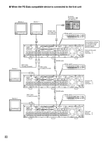
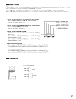
When the PS, Data compatible devices are connected to the first and third units, No. 7: OFF
 |
View all Panasonic WJHD316A manuals
Add to My Manuals
Save this manual to your list of manuals |
Page 82 highlights
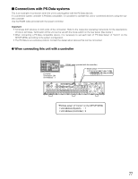
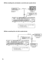
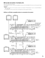
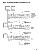
G When the PS·Data compatible devices are connected to the first and third units Monitor 2 Monitor 1 PS · Data Compatible System Controller Controller Termination: ON Unit Address: 1 RS485 cable (provided with the controller) Mode switch ON (No. 7: OFF) (No. 8: OFF) 12345678 3 1 1 SERIAL ALARM 4 2 AUDIO IN AUDIO OUT CASCADE OUT 2 MONITOR OUT CASCADE IN MONITOR (VGA) ALARM/CONTROL 16 15 14 13 12 11 10 9 8 7 IN OUT 16 15 14 13 12 11 10 9 8 7 VIDEO 1 8 MODE 2 1 COPY 1 DATA 6 5 RS485(CAMERA) 10/100BASE-T EXT STORAGE 4 3 2 1 6 5 4 3 2 1 SIGNAL GND POWER AC IN Unit Address settings of "PS·Data Setup" of "Comm" on the SETUP MENU First unit (this unit) System : 1 Controller : 2 Monitor 1 BNC Cable (Locally procured) BNC Cable (Locally procured) RS485 cable Mode switch ON (No. 7: OFF) (No. 8: OFF) 12345678 3 1 1 SERIAL ALARM 4 2 AUDIO IN AUDIO OUT CASCADE OUT 2 MONITOR OUT CASCADE IN MONITOR (VGA) ALARM/CONTROL 16 15 14 13 12 11 10 9 8 7 IN OUT 16 15 14 13 12 11 10 9 8 7 VIDEO 1 8 MODE 2 1 COPY 1 DATA 6 5 RS485(CAMERA) 10/100BASE-T EXT STORAGE 4 3 2 1 6 5 4 3 2 1 SIGNAL GND POWER AC IN Second unit System : 2 Controller : 3 Monitor 1 BNC Cable (Locally procured) RS485 cable Mode switch ON (No. 7: OFF) (No. 8: OFF) 12345678 3 1 1 SERIAL ALARM 4 2 AUDIO IN AUDIO OUT CASCADE OUT 2 MONITOR OUT CASCADE IN MONITOR (VGA) ALARM/CONTROL 16 15 14 13 12 11 10 9 8 7 IN OUT 16 15 14 13 12 11 10 9 8 7 VIDEO 1 8 MODE 2 1 COPY 1 DATA 6 5 RS485(CAMERA) 10/100BASE-T EXT STORAGE 4 3 2 1 6 5 4 3 2 1 SIGNAL GND POWER Third unit AC IN System : 3 Controller : 4 RS485 cable POWER UNIT 901 ALARM 78 456 23 ALARM Coaxial communication unit RESET SUSPEND SET UP ALARM SUSPEND SET ESC ON OFF 1 2 3 4 Termination: ON Data Multiplex Unit WJ-MP204 Unit Address: 5 82
-
 1
1 -
2
-
3
-
4
-
5
-
6
-
7
-
8
-
9
-
10
-
11
-
12
-
13
-
14
-
15
-
16
-
17
-
18
-
19
-
20
-
21
-
22
-
23
-
24
-
25
-
26
-
27
-
28
-
29
-
30
-
31
-
32
-
33
-
34
-
35
-
36
-
37
-
38
-
39
-
40
-
41
-
42
-
43
-
44
-
45
-
46
-
47
-
48
-
49
-
50
-
51
-
52
-
53
-
54
-
55
-
56
-
57
-
58
-
59
-
60
-
61
-
62
-
63
-
64
-
65
-
66
-
67
-
68
-
69
-
70
-
71
-
72
-
73
-
74
-
75
-
76
-
 77
77 -
 78
78 -
 79
79 -
 80
80 -
 81
81 -
 82
82 -
 83
83 -
 84
84 -
 85
85 -
 86
86 -
 87
87 -
88
-
89
-
90
-
91
-
92
-
93
-
94
-
95
-
96
-
97
-
98
-
99
-
100
-
101
-
102
-
103
-
104
-
105
-
106
-
107
-
108
-
109
-
110
-
111
-
112
-
113
-
114
-
115
-
116
-
117
-
118
-
119
-
120
-
121
-
122
-
123
-
124
-
125
-
126
-
127
-
128
-
129
-
130
-
131
-
132
-
133
-
134
-
135
-
136
-
137
-
138
-
139
-
140
-
141
-
142
-
143
-
144
-
145
-
146
-
147
-
148
-
149
-
150
-
151
-
152
-
153
-
154
-
155
-
156
-
157
-
158
-
159
-
160
-
161
-
162
-
163
-
164
-
165
-
166
-
167
-
168
-
169
-
170
-
171
-
172
-
173
-
174
-
175
-
176
-
177
-
178
-
179
-
180
-
181
-
182
 |
 |
