Panasonic WJHD316A WJHD309A User Guide - Page 74
Connections with an extension unit
 |
View all Panasonic WJHD316A manuals
Add to My Manuals
Save this manual to your list of manuals |
Page 74 highlights
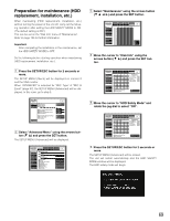
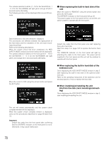
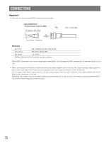
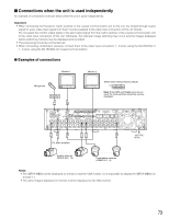
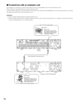
I Connections with an extension unit An example of connections is shown below when the unit is used together with an optional extension unit. This unit can be connected with up to seven extension units. Connect the EXT IN port on the rear panel of the extension unit and the EXT STORAGE port on the rear panel of this unit using the cable provided with the optional extension unit. Important: • Use the cable provided with the optional extension unit. • Fix the cables with the cable clamp (provided with each unit) to prevent disconnection or unstable connections that may cause recording failures or an unstable system. How to fix the cable clamp Cable Clamp COPY 10/100BASE-T 2 EXIT STORAGE 1 2 1 Fixing screw Remove this screw from the unit and fix the cables with the cable clamp using the screw removed from the unit. 3 1 1 SERIAL ALARM 4 2 AUDIO IN AUDIO OUT CASCADE OUT 2 MONITOR OUT CASCADE IN MONITOR (VGA) ALARM/CONTROL 16 15 14 13 12 11 10 9 8 7 IN OUT 16 15 14 13 12 11 10 9 8 7 VIDEO 1 8 MODE 2 1 COPY 1 DATA 6 5 RS485(CAMERA) 10/100BASE-T EXT STORAGE 4 3 2 1 6 5 4 3 2 1 This unit Cable (attached to the extension unit) SIGNAL GND POWER AC IN EXT IN OUT 21 SIGNAL GND POWER AC IN Cable Clamp EXT IN OUT 21 Fixing screw Remove this screw from the unit and fix the cables with the cable clamp using the screw removed from the unit. How to fix the cable clamp Extension unit (WJ-HDE300 series) 74
-
 1
1 -
2
-
3
-
4
-
5
-
6
-
7
-
8
-
9
-
10
-
11
-
12
-
13
-
14
-
15
-
16
-
17
-
18
-
19
-
20
-
21
-
22
-
23
-
24
-
25
-
26
-
27
-
28
-
29
-
30
-
31
-
32
-
33
-
34
-
35
-
36
-
37
-
38
-
39
-
40
-
41
-
42
-
43
-
44
-
45
-
46
-
47
-
48
-
49
-
50
-
51
-
52
-
53
-
54
-
55
-
56
-
57
-
58
-
59
-
60
-
61
-
62
-
63
-
64
-
65
-
66
-
67
-
68
-
 69
69 -
 70
70 -
 71
71 -
 72
72 -
 73
73 -
 74
74 -
 75
75 -
 76
76 -
 77
77 -
 78
78 -
 79
79 -
80
-
81
-
82
-
83
-
84
-
85
-
86
-
87
-
88
-
89
-
90
-
91
-
92
-
93
-
94
-
95
-
96
-
97
-
98
-
99
-
100
-
101
-
102
-
103
-
104
-
105
-
106
-
107
-
108
-
109
-
110
-
111
-
112
-
113
-
114
-
115
-
116
-
117
-
118
-
119
-
120
-
121
-
122
-
123
-
124
-
125
-
126
-
127
-
128
-
129
-
130
-
131
-
132
-
133
-
134
-
135
-
136
-
137
-
138
-
139
-
140
-
141
-
142
-
143
-
144
-
145
-
146
-
147
-
148
-
149
-
150
-
151
-
152
-
153
-
154
-
155
-
156
-
157
-
158
-
159
-
160
-
161
-
162
-
163
-
164
-
165
-
166
-
167
-
168
-
169
-
170
-
171
-
172
-
173
-
174
-
175
-
176
-
177
-
178
-
179
-
180
-
181
-
182
 |
 |
