Panasonic WJHD316A WJHD309A User Guide - Page 89
Connection with the Uninterruptible Power System UPS, Connection of the control output, ALARM/CONTROL
 |
View all Panasonic WJHD316A manuals
Add to My Manuals
Save this manual to your list of manuals |
Page 89 highlights
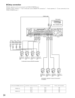
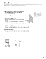
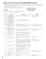
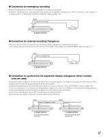
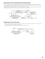
G Connection with the Uninterruptible Power System (UPS) This is an example of connection with the uninterruptible power system (UPS) to be installed to protect from a power outage. When a signal is supplied to the outage detection I/O terminals from the uninterruptible power system (UPS), internal processing (stops recording safely) will be started to shut off the power supply for this unit. After completing the internal processing, a signal will be supplied from the outage processing end output terminal to the uninterruptible power system (UPS). Then, the power supply to this unit can be suspended. This unit !3 (Earth) (COM) (Outage detection I/O) (Outage processing end output) (Detection) (Shutdown) @3 !9 * Refer to the operating instructions of the used product for further information about connection of the UPS side. ALARM/CONTROL Power cable Uninterruptible power system (UPS) To an AC outlet G Connection of the control output • When an alarm device such as a buzzer or a lamp is connected, the signal output from Pin Nos. 15 - 18 can be used to notify the status by sounding a buzzer or lighting a lamp. • The following example is of a connection with the HDD error output (pin no. 16). (Earth) !3 (HDD error output) !6 Alarming device ALARM/CONTROL Relay, etc. Install according to your needs 89
-
 1
1 -
2
-
3
-
4
-
5
-
6
-
7
-
8
-
9
-
10
-
11
-
12
-
13
-
14
-
15
-
16
-
17
-
18
-
19
-
20
-
21
-
22
-
23
-
24
-
25
-
26
-
27
-
28
-
29
-
30
-
31
-
32
-
33
-
34
-
35
-
36
-
37
-
38
-
39
-
40
-
41
-
42
-
43
-
44
-
45
-
46
-
47
-
48
-
49
-
50
-
51
-
52
-
53
-
54
-
55
-
56
-
57
-
58
-
59
-
60
-
61
-
62
-
63
-
64
-
65
-
66
-
67
-
68
-
69
-
70
-
71
-
72
-
73
-
74
-
75
-
76
-
77
-
78
-
79
-
80
-
81
-
82
-
83
-
 84
84 -
 85
85 -
 86
86 -
 87
87 -
 88
88 -
 89
89 -
 90
90 -
 91
91 -
 92
92 -
 93
93 -
 94
94 -
95
-
96
-
97
-
98
-
99
-
100
-
101
-
102
-
103
-
104
-
105
-
106
-
107
-
108
-
109
-
110
-
111
-
112
-
113
-
114
-
115
-
116
-
117
-
118
-
119
-
120
-
121
-
122
-
123
-
124
-
125
-
126
-
127
-
128
-
129
-
130
-
131
-
132
-
133
-
134
-
135
-
136
-
137
-
138
-
139
-
140
-
141
-
142
-
143
-
144
-
145
-
146
-
147
-
148
-
149
-
150
-
151
-
152
-
153
-
154
-
155
-
156
-
157
-
158
-
159
-
160
-
161
-
162
-
163
-
164
-
165
-
166
-
167
-
168
-
169
-
170
-
171
-
172
-
173
-
174
-
175
-
176
-
177
-
178
-
179
-
180
-
181
-
182
 |
 |
