Dell PowerConnect B-RX16 Installation Guide - Page 123
Using virtual cable testing to diagnose a cable, Configuration notes, Command syntax
 |
View all Dell PowerConnect B-RX16 manuals
Add to My Manuals
Save this manual to your list of manuals |
Page 123 highlights
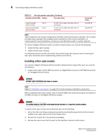
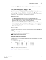
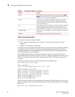
Testing network connectivity 4 Refer to the BigIron RX Series Configuration Guide for information about the command syntax. Using virtual cable testing to diagnose a cable BigIron RX devices support Virtual Cable Test (VCT) technology. VCT technology enables you to diagnose a conductor (wire or cable) by sending a pulsed signal into the conductor, then examining the reflection of that pulse. This method of cable analysis is referred to as Time Domain Reflectometry (TDR). By examining the reflection, the Brocade device can detect and report cable statistics such as, local and remote link pair, cable length, and link status. Configuration notes • This feature is supported on copper ports only. It is not supported on fiber ports. • The port to which the cable is connected must be enabled when you issue the command to diagnose the cable. If the port is disabled, the command is rejected. • If the port is operating at 100 Mbps half-duplex, the TDR test on one pair will fail. • If the remote pair is set to forced 100 Mbps, any change in MDI or MDIX may cause the device to interpret the Multilevel Threshold-3 (MLT-3) as a reflected pulse, in which case, the device will report a faulty condition. In this scenario, it is recommended that you run the TDR test a few times for accurate results. Command syntax To diagnose a cable using TDR, enter commands such as the following at the Privileged EXEC level of the CLI: BigIron RX# phy cable-diag tdr 1 The above command diagnoses the cable attached to port 1. Syntax: phy cable-diag tdr Viewing the results of the cable analysis To display the results of the cable analysis, enter a command such as the following at the Privileged EXEC level of the CLI: BigIron RX#sh cable-diag tdr 1 Port Speed Local pair Pair Length Remote pair Pair status 01 1000M Pair A
-
 1
1 -
2
-
3
-
4
-
5
-
6
-
7
-
8
-
9
-
10
-
11
-
12
-
13
-
14
-
15
-
16
-
17
-
18
-
19
-
20
-
21
-
22
-
23
-
24
-
25
-
26
-
27
-
28
-
29
-
30
-
31
-
32
-
33
-
34
-
35
-
36
-
37
-
38
-
39
-
40
-
41
-
42
-
43
-
44
-
45
-
46
-
47
-
48
-
49
-
50
-
51
-
52
-
53
-
54
-
55
-
56
-
57
-
58
-
59
-
60
-
61
-
62
-
63
-
64
-
65
-
66
-
67
-
68
-
69
-
70
-
71
-
72
-
73
-
74
-
75
-
76
-
77
-
78
-
79
-
80
-
81
-
82
-
83
-
84
-
85
-
86
-
87
-
88
-
89
-
90
-
91
-
92
-
93
-
94
-
95
-
96
-
97
-
98
-
99
-
100
-
101
-
102
-
103
-
104
-
105
-
106
-
107
-
108
-
109
-
110
-
111
-
112
-
113
-
114
-
115
-
116
-
117
-
 118
118 -
 119
119 -
 120
120 -
 121
121 -
 122
122 -
 123
123 -
 124
124 -
 125
125 -
 126
126 -
 127
127 -
 128
128 -
129
-
130
-
131
-
132
-
133
-
134
-
135
-
136
-
137
-
138
-
139
-
140
-
141
-
142
-
143
-
144
-
145
-
146
-
147
-
148
-
149
-
150
-
151
-
152
-
153
-
154
-
155
-
156
-
157
-
158
-
159
-
160
-
161
-
162
-
163
-
164
-
165
-
166
-
167
-
168
-
169
-
170
-
171
-
172
-
173
-
174
-
175
-
176
-
177
-
178
-
179
-
180
-
181
-
182
-
183
-
184
-
185
-
186
-
187
-
188
-
189
-
190
-
191
-
192
-
193
-
194
-
195
-
196
-
197
-
198
-
199
-
200
-
201
-
202
-
203
-
204
-
205
-
206
-
207
-
208
-
209
-
210
-
211
-
212
-
213
-
214
-
215
-
216
-
217
-
218
-
219
-
220
-
221
-
222
-
223
-
224
-
225
-
226
-
227
-
228
-
229
-
230
-
231
-
232
-
233
-
234
-
235
-
236
-
237
-
238
-
239
-
240
 |
 |