Dell PowerConnect B-RX16 Installation Guide - Page 27
-port 1 Gigabit Ethernet interface module (Mini RJ 21 Copper)
 |
View all Dell PowerConnect B-RX16 manuals
Add to My Manuals
Save this manual to your list of manuals |
Page 27 highlights
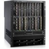
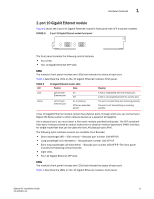
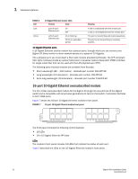
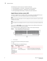
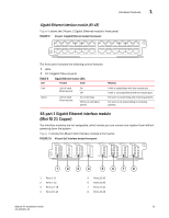
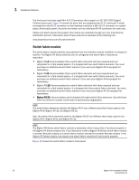
Hardware features 1 Gigabit Ethernet interface module (RJ-45) Figure 9 shows the 24-port 1 Gigabit Ethernet module's front panel. FIGURE 9 24-port 1 Gigabit Ethernet module front panel The front panel includes the following control features: • LEDs • 24 1-Gigabit Ethernet ports TABLE 6 Gigabit Ethernet module LEDs LED Position State Link Active Left of each Ethernet port Left of each Ethernet port On Off On or blinking Off for an extended period Meaning A link is established with the remote port. A link is not established with the remote port. The port is transmitting and receiving packets. The port is not transmitting or receiving packets. 48-port 1 Gigabit Ethernet interface module (Mini RJ 21 Copper) The interface modules are hot swappable, which means you can remove and replace them without powering down the system. Figure 10 shows the 48-port GoC interface module's front panel. FIGURE 10 48-port GoC interface module front panel 6 12 18 24 30 36 42 48 1 7 13 19 25 31 37 43 1 2 3 4 5 6 7 8 1 Ports 1 -6 2 Ports 7-12 3 Ports 13 -18 4 Ports 19 -24 5 Ports 25-30 6 Ports 31-36 7 Ports 37-42 8 Ports 43-48 BigIron RX Installation Guide 15 53-1001811-01
-
 1
1 -
2
-
3
-
4
-
5
-
6
-
7
-
8
-
9
-
10
-
11
-
12
-
13
-
14
-
15
-
16
-
17
-
18
-
19
-
20
-
21
-
 22
22 -
 23
23 -
 24
24 -
 25
25 -
 26
26 -
 27
27 -
 28
28 -
 29
29 -
 30
30 -
 31
31 -
 32
32 -
33
-
34
-
35
-
36
-
37
-
38
-
39
-
40
-
41
-
42
-
43
-
44
-
45
-
46
-
47
-
48
-
49
-
50
-
51
-
52
-
53
-
54
-
55
-
56
-
57
-
58
-
59
-
60
-
61
-
62
-
63
-
64
-
65
-
66
-
67
-
68
-
69
-
70
-
71
-
72
-
73
-
74
-
75
-
76
-
77
-
78
-
79
-
80
-
81
-
82
-
83
-
84
-
85
-
86
-
87
-
88
-
89
-
90
-
91
-
92
-
93
-
94
-
95
-
96
-
97
-
98
-
99
-
100
-
101
-
102
-
103
-
104
-
105
-
106
-
107
-
108
-
109
-
110
-
111
-
112
-
113
-
114
-
115
-
116
-
117
-
118
-
119
-
120
-
121
-
122
-
123
-
124
-
125
-
126
-
127
-
128
-
129
-
130
-
131
-
132
-
133
-
134
-
135
-
136
-
137
-
138
-
139
-
140
-
141
-
142
-
143
-
144
-
145
-
146
-
147
-
148
-
149
-
150
-
151
-
152
-
153
-
154
-
155
-
156
-
157
-
158
-
159
-
160
-
161
-
162
-
163
-
164
-
165
-
166
-
167
-
168
-
169
-
170
-
171
-
172
-
173
-
174
-
175
-
176
-
177
-
178
-
179
-
180
-
181
-
182
-
183
-
184
-
185
-
186
-
187
-
188
-
189
-
190
-
191
-
192
-
193
-
194
-
195
-
196
-
197
-
198
-
199
-
200
-
201
-
202
-
203
-
204
-
205
-
206
-
207
-
208
-
209
-
210
-
211
-
212
-
213
-
214
-
215
-
216
-
217
-
218
-
219
-
220
-
221
-
222
-
223
-
224
-
225
-
226
-
227
-
228
-
229
-
230
-
231
-
232
-
233
-
234
-
235
-
236
-
237
-
238
-
239
-
240
 |
 |