Dell PowerConnect B-RX16 Installation Guide - Page 158
Installing a new fiber-optic transceiver
 |
View all Dell PowerConnect B-RX16 manuals
Add to My Manuals
Save this manual to your list of manuals |
Page 158 highlights
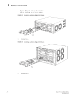
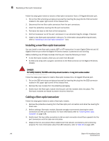
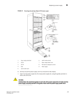
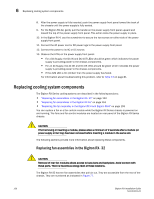
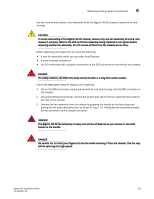
6 Replacing a fiber-optic transceiver Follow the steps given below to remove a fiber-optic transceiver from a 10 Gigabit Ethernet port. 1. Put on the ESD wrist strap and ground yourself by inserting the plug into the ESD connector located in the upper right corner of the chassis front. 2. Disconnect the two fiber cable connectors from the port connectors. 3. Insert the protective covering into the port connectors. 4. Pull down the latch on the front of the transceiver. 5. Pull the transceiver out of the port, and place it in an anti-static bag for storage, if desired. 6. Install a new fiber-optic transceiver in the port. For information about performing this task, refer to "Installing a new fiber-optic transceiver" next. Installing a new fiber-optic transceiver You can install a new fiber-optic module (SFP or XFP transceiver) in each Gigabit Ethernet and 10 Gigabit Ethernet port while the BigIron RX Series chassis is powered on and running. Before installing one of these modules into the port, have the following on hand: • A new fiber-optic module, which you can order from Brocade • An ESD wrist strap with a plug for connection to the ESD connector on the BigIron RX Series chassis DANGER For safety reasons, the ESD wrist strap should contain a 1 meg ohm series resistor. Follow the steps given below to install a fiber-optic module into a 10 Gigabit Ethernet port. 1. Put on the ESD wrist strap and ground yourself by inserting the plug into the ESD connector located in the upper right corner of the chassis front. 2. Remove the new module from its protective packaging. 3. Gently insert the fiber-optic module into the port until the module clicks into place. The fiber-optic modules are keyed to prevent incorrect insertion. Cabling a fiber-optic transceiver Follow the steps given below to cable a fiber-optic module. 1. Remove the protective covering from the fiber-optic port connectors and store the covering for future use. 2. Before cabling a fiber-optic module, Brocade strongly recommends cleaning the cable connectors and the port connectors. For more information,refer to "Cleaning fiber optic modules" on page 108. 3. Gently insert the two cable connectors (a tab on each connector should face upward) into the port connectors until the tabs lock into place. 4. Observe the link and active LEDs to determine if the network connections are functioning properly. For more information about the LED indicators, refer to Table 16 on page 109. 146 BigIron RX Installation Guide 53-1001811-01
-
 1
1 -
2
-
3
-
4
-
5
-
6
-
7
-
8
-
9
-
10
-
11
-
12
-
13
-
14
-
15
-
16
-
17
-
18
-
19
-
20
-
21
-
22
-
23
-
24
-
25
-
26
-
27
-
28
-
29
-
30
-
31
-
32
-
33
-
34
-
35
-
36
-
37
-
38
-
39
-
40
-
41
-
42
-
43
-
44
-
45
-
46
-
47
-
48
-
49
-
50
-
51
-
52
-
53
-
54
-
55
-
56
-
57
-
58
-
59
-
60
-
61
-
62
-
63
-
64
-
65
-
66
-
67
-
68
-
69
-
70
-
71
-
72
-
73
-
74
-
75
-
76
-
77
-
78
-
79
-
80
-
81
-
82
-
83
-
84
-
85
-
86
-
87
-
88
-
89
-
90
-
91
-
92
-
93
-
94
-
95
-
96
-
97
-
98
-
99
-
100
-
101
-
102
-
103
-
104
-
105
-
106
-
107
-
108
-
109
-
110
-
111
-
112
-
113
-
114
-
115
-
116
-
117
-
118
-
119
-
120
-
121
-
122
-
123
-
124
-
125
-
126
-
127
-
128
-
129
-
130
-
131
-
132
-
133
-
134
-
135
-
136
-
137
-
138
-
139
-
140
-
141
-
142
-
143
-
144
-
145
-
146
-
147
-
148
-
149
-
150
-
151
-
152
-
 153
153 -
 154
154 -
 155
155 -
 156
156 -
 157
157 -
 158
158 -
 159
159 -
 160
160 -
 161
161 -
 162
162 -
 163
163 -
164
-
165
-
166
-
167
-
168
-
169
-
170
-
171
-
172
-
173
-
174
-
175
-
176
-
177
-
178
-
179
-
180
-
181
-
182
-
183
-
184
-
185
-
186
-
187
-
188
-
189
-
190
-
191
-
192
-
193
-
194
-
195
-
196
-
197
-
198
-
199
-
200
-
201
-
202
-
203
-
204
-
205
-
206
-
207
-
208
-
209
-
210
-
211
-
212
-
213
-
214
-
215
-
216
-
217
-
218
-
219
-
220
-
221
-
222
-
223
-
224
-
225
-
226
-
227
-
228
-
229
-
230
-
231
-
232
-
233
-
234
-
235
-
236
-
237
-
238
-
239
-
240
 |
 |