Dell PowerConnect B-RX16 Installation Guide - Page 21
PCMCIA slots, Console port, 100/1000 Ethernet port
 |
View all Dell PowerConnect B-RX16 manuals
Add to My Manuals
Save this manual to your list of manuals |
Page 21 highlights
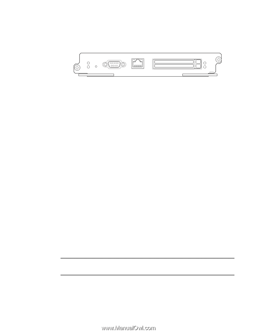
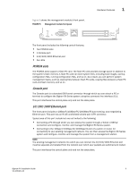
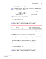
Hardware features 1 Figure 5 shows the management module's front panel. FIGURE 5 Management module front panel Pwr Active RX-BI-MR Console 10/100/1000 Port 1 Port 2 The front panel includes the following control features: • Two PCMCIA slots • A Console port • A 10/100/1000 Ethernet port • Six LEDs PCMCIA slots The PCMCIA slots support a flash PC card. The flash PC card provides storage space in addition to the system's flash memory. A flash PC card can store system files, including boot images, startup configuration files, running configuration files, and so on. As a result, you can perform system management tasks, such as copying files between flash PC cards, copying files between a flash PC card and flash memory, and so on. Console port The Console port is a standard DB-9 serial connector through which you can attach a PC or terminal to configure the BigIron RX Series system using the command line interface (CLI). This port interfaces the control plane only and not the data plane. 10/100/1000 Ethernet port The front panel includes a 10BaseT/100BaseTX/1000BaseTX auto-sensing, auto-negotiating Ethernet port. This port has an RJ-45 unshielded twisted pair (UTP) connector. Typical uses of this port include but are not limited to the following: • Connecting a PC through which you can access the system through a Telnet or SSHv2 connection and configure, monitor, and manage the BigIron RX Series system. • Connecting to the 10BaseT/100BaseTX/1000BaseTX port of a switch or router, for connectivity to your existing management network. You can then access the BigIron RX Series system and configure, monitor, and manage the system from a management station. NOTE The existing management network into which you can connect the 10/100/1000 Ethernet port must be separate and isolated from the network over which user packets are switched and routed. This port interfaces the control plane only and not the data plane. BigIron RX Installation Guide 9 53-1001811-01
-
 1
1 -
2
-
3
-
4
-
5
-
6
-
7
-
8
-
9
-
10
-
11
-
12
-
13
-
14
-
15
-
 16
16 -
 17
17 -
 18
18 -
 19
19 -
 20
20 -
 21
21 -
 22
22 -
 23
23 -
 24
24 -
 25
25 -
 26
26 -
27
-
28
-
29
-
30
-
31
-
32
-
33
-
34
-
35
-
36
-
37
-
38
-
39
-
40
-
41
-
42
-
43
-
44
-
45
-
46
-
47
-
48
-
49
-
50
-
51
-
52
-
53
-
54
-
55
-
56
-
57
-
58
-
59
-
60
-
61
-
62
-
63
-
64
-
65
-
66
-
67
-
68
-
69
-
70
-
71
-
72
-
73
-
74
-
75
-
76
-
77
-
78
-
79
-
80
-
81
-
82
-
83
-
84
-
85
-
86
-
87
-
88
-
89
-
90
-
91
-
92
-
93
-
94
-
95
-
96
-
97
-
98
-
99
-
100
-
101
-
102
-
103
-
104
-
105
-
106
-
107
-
108
-
109
-
110
-
111
-
112
-
113
-
114
-
115
-
116
-
117
-
118
-
119
-
120
-
121
-
122
-
123
-
124
-
125
-
126
-
127
-
128
-
129
-
130
-
131
-
132
-
133
-
134
-
135
-
136
-
137
-
138
-
139
-
140
-
141
-
142
-
143
-
144
-
145
-
146
-
147
-
148
-
149
-
150
-
151
-
152
-
153
-
154
-
155
-
156
-
157
-
158
-
159
-
160
-
161
-
162
-
163
-
164
-
165
-
166
-
167
-
168
-
169
-
170
-
171
-
172
-
173
-
174
-
175
-
176
-
177
-
178
-
179
-
180
-
181
-
182
-
183
-
184
-
185
-
186
-
187
-
188
-
189
-
190
-
191
-
192
-
193
-
194
-
195
-
196
-
197
-
198
-
199
-
200
-
201
-
202
-
203
-
204
-
205
-
206
-
207
-
208
-
209
-
210
-
211
-
212
-
213
-
214
-
215
-
216
-
217
-
218
-
219
-
220
-
221
-
222
-
223
-
224
-
225
-
226
-
227
-
228
-
229
-
230
-
231
-
232
-
233
-
234
-
235
-
236
-
237
-
238
-
239
-
240
 |
 |