Dell PowerConnect B-RX16 Installation Guide - Page 40
Installing a BigIron RX-4 switch
 |
View all Dell PowerConnect B-RX16 manuals
Add to My Manuals
Save this manual to your list of manuals |
Page 40 highlights
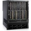
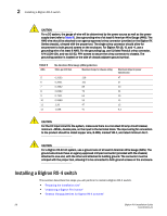
2 Installing a BigIron RX-4 switch CAUTION For a DC system, the gauge of wire will be determined by the power source as well as the power supply draw (refer to Table 9). Use a grounding wire of at least 6 American Wire Gauge (AWG). The AWG wire should be attached to an agency-approved crimp connector (provided on the BigIron RX Series chassis), crimped with the proper tool. The single crimp connector should allow for securement to both ground screws on the enclosure. For BigIron RX-16, -8, and -4, use a grounding wire of at least 6 AWG. For the grounding lug, use UL-listed Panduit crimp connector, P/N LCD6-10A, and two 10-32, PPH screws to secure the crimp connector to chassis. The grounding position is located on the side of chassis adjacent ground symbol. TABLE 9 AWG 5 6 7 8 9 10 11 12 The American Wire Gauge (AWG) guidelines Ohms per 100 feet Maximum Amps for chassis wiring 0.3133 118 0.3951 101 0.4982 89 0.6282 73 0.7921 64 0.9989 55 1.26 47 1.588 41 Maximum Amps for power transmission 47 37 30 24 19 15 12 9.3 CAUTION For the DC input circuit to the system, make sure there is a UL-Listed 30 amp circuit breaker, minimum -48Vdc, double pole, on the input to the terminal block. The input wiring for connection to the product should be Listed copper wire, 8 AWG, marked VW-1, and rated minimum 9o C. CAUTION For a BigIron RX-32 AC system, use a ground wire of at least 6 American Wire Gauge (AWG). The ground wire should have an agency-approved crimped connector (provided with the chassis) attached to one end, with the other end attached to building ground. The connector must be crimped with the proper tool, allowing it to be connected to both ground screws on the enclosure. Installing a BigIron RX-4 switch This section describes the steps you will perform to install a BigIron RX-4 switch: • "Preparing the installation site" • "Unpacking a BigIron RX-4 switch" • "Chassis lifting guidelines for BigIron RX-4 switches" 28 BigIron RX Installation Guide 53-1001811-01
-
 1
1 -
2
-
3
-
4
-
5
-
6
-
7
-
8
-
9
-
10
-
11
-
12
-
13
-
14
-
15
-
16
-
17
-
18
-
19
-
20
-
21
-
22
-
23
-
24
-
25
-
26
-
27
-
28
-
29
-
30
-
31
-
32
-
33
-
34
-
 35
35 -
 36
36 -
 37
37 -
 38
38 -
 39
39 -
 40
40 -
 41
41 -
 42
42 -
 43
43 -
 44
44 -
 45
45 -
46
-
47
-
48
-
49
-
50
-
51
-
52
-
53
-
54
-
55
-
56
-
57
-
58
-
59
-
60
-
61
-
62
-
63
-
64
-
65
-
66
-
67
-
68
-
69
-
70
-
71
-
72
-
73
-
74
-
75
-
76
-
77
-
78
-
79
-
80
-
81
-
82
-
83
-
84
-
85
-
86
-
87
-
88
-
89
-
90
-
91
-
92
-
93
-
94
-
95
-
96
-
97
-
98
-
99
-
100
-
101
-
102
-
103
-
104
-
105
-
106
-
107
-
108
-
109
-
110
-
111
-
112
-
113
-
114
-
115
-
116
-
117
-
118
-
119
-
120
-
121
-
122
-
123
-
124
-
125
-
126
-
127
-
128
-
129
-
130
-
131
-
132
-
133
-
134
-
135
-
136
-
137
-
138
-
139
-
140
-
141
-
142
-
143
-
144
-
145
-
146
-
147
-
148
-
149
-
150
-
151
-
152
-
153
-
154
-
155
-
156
-
157
-
158
-
159
-
160
-
161
-
162
-
163
-
164
-
165
-
166
-
167
-
168
-
169
-
170
-
171
-
172
-
173
-
174
-
175
-
176
-
177
-
178
-
179
-
180
-
181
-
182
-
183
-
184
-
185
-
186
-
187
-
188
-
189
-
190
-
191
-
192
-
193
-
194
-
195
-
196
-
197
-
198
-
199
-
200
-
201
-
202
-
203
-
204
-
205
-
206
-
207
-
208
-
209
-
210
-
211
-
212
-
213
-
214
-
215
-
216
-
217
-
218
-
219
-
220
-
221
-
222
-
223
-
224
-
225
-
226
-
227
-
228
-
229
-
230
-
231
-
232
-
233
-
234
-
235
-
236
-
237
-
238
-
239
-
240
 |
 |