Dell PowerConnect B-RX16 Installation Guide - Page 78
Using the Insertion or Extraction tool,
 |
View all Dell PowerConnect B-RX16 manuals
Add to My Manuals
Save this manual to your list of manuals |
Page 78 highlights
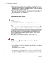
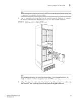
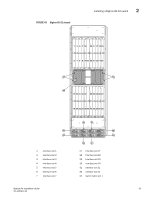
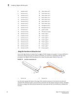
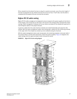
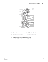
2 Installing a BigIron RX-32 switch 8 Interface slot 8 9 Interface slot 9 10 Interface slot 10 11 Interface slot 11 12 Interface slot 12 13 Interface slot 13 14 Interface slot 14 15 Interface slot 15 16 Interface slot 16 17 Interface slot 17 18 Interface slot 18 19 Interface slot 19 20 Interface slot 20 21 Interface slot 21 22 Interface slot 22 23 Interface slot 23 24 Interface slot 24 25 Interface slot 25 26 Interface slot 26 34 Switch fabric slot 2 35 Switch fabric slot 3 36 Switch fabric slot 4 37 Switch fabric slot 5 38 Switch fabric slot 6 39 Switch fabric slot 7 40 Switch fabric slot 8 41 Management slot 1 42 Management slot 2 43 Captive screws 44 ESD strap connector 45 Power supply 1 46 Power supply 2 47 Power supply 3 48 Power supply 4 49 Power supply 5 50 Power supply 6 51 Power supply 7 52 Power supply 8 Using the Insertion or Extraction tool Due to the high density of cables that the BigIron RX-32 chassis can support, it may be difficult to insert and remove the RJ-45 and optical connectors. An insertion or extraction tool has been provided in the BigIron RX-32 accessory kit to make this task easier. Refer to Figure 44. FIGURE 44 Insertion or extraction tool 2 1 1 Hooked tab 2 Stepped tab Use the tool to grasp the boot or the plug of the modular connector at its narrow end (the end closest to the attached cable), and insert the connector into the proper interface module. Grasping the boot or plug at the wide end during insertion may cause the tool to be difficult to release and remove. 66 BigIron RX Installation Guide 53-1001811-01
-
 1
1 -
2
-
3
-
4
-
5
-
6
-
7
-
8
-
9
-
10
-
11
-
12
-
13
-
14
-
15
-
16
-
17
-
18
-
19
-
20
-
21
-
22
-
23
-
24
-
25
-
26
-
27
-
28
-
29
-
30
-
31
-
32
-
33
-
34
-
35
-
36
-
37
-
38
-
39
-
40
-
41
-
42
-
43
-
44
-
45
-
46
-
47
-
48
-
49
-
50
-
51
-
52
-
53
-
54
-
55
-
56
-
57
-
58
-
59
-
60
-
61
-
62
-
63
-
64
-
65
-
66
-
67
-
68
-
69
-
70
-
71
-
72
-
 73
73 -
 74
74 -
 75
75 -
 76
76 -
 77
77 -
 78
78 -
 79
79 -
 80
80 -
 81
81 -
 82
82 -
 83
83 -
84
-
85
-
86
-
87
-
88
-
89
-
90
-
91
-
92
-
93
-
94
-
95
-
96
-
97
-
98
-
99
-
100
-
101
-
102
-
103
-
104
-
105
-
106
-
107
-
108
-
109
-
110
-
111
-
112
-
113
-
114
-
115
-
116
-
117
-
118
-
119
-
120
-
121
-
122
-
123
-
124
-
125
-
126
-
127
-
128
-
129
-
130
-
131
-
132
-
133
-
134
-
135
-
136
-
137
-
138
-
139
-
140
-
141
-
142
-
143
-
144
-
145
-
146
-
147
-
148
-
149
-
150
-
151
-
152
-
153
-
154
-
155
-
156
-
157
-
158
-
159
-
160
-
161
-
162
-
163
-
164
-
165
-
166
-
167
-
168
-
169
-
170
-
171
-
172
-
173
-
174
-
175
-
176
-
177
-
178
-
179
-
180
-
181
-
182
-
183
-
184
-
185
-
186
-
187
-
188
-
189
-
190
-
191
-
192
-
193
-
194
-
195
-
196
-
197
-
198
-
199
-
200
-
201
-
202
-
203
-
204
-
205
-
206
-
207
-
208
-
209
-
210
-
211
-
212
-
213
-
214
-
215
-
216
-
217
-
218
-
219
-
220
-
221
-
222
-
223
-
224
-
225
-
226
-
227
-
228
-
229
-
230
-
231
-
232
-
233
-
234
-
235
-
236
-
237
-
238
-
239
-
240
 |
 |