Dell PowerConnect B-RX16 Installation Guide - Page 93
TABLE 13, Desired and abnormal LED states after system power
 |
View all Dell PowerConnect B-RX16 manuals
Add to My Manuals
Save this manual to your list of manuals |
Page 93 highlights
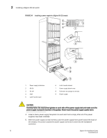
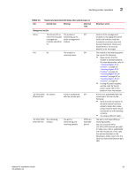
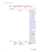
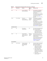
Verifying proper operation 2 TABLE 13 LED Desired and abnormal LED states after system power on Desired state Meaning Abnormal state Management module Active The Active LED on The module is Off one of the installed functioning as the management active management modules should be module. on. Pwr On The module is Off receiving power. 10/100/1000 On (Green) Ethernet Port A link is established Off with the remote port. 10/100/1000 On or blinking Ethernet Port (Yellow) The port is transmitting and receiving packets. Off for an extended period Meaning or action Neither of the management modules is managing the switch fabric and interface modules. A problem could have occurred during initialization. Check your attached PC or terminal for possible error messages. The module is not receiving power. You can do the following: • Make certain that the module is installed properly. For more information, refer to "Installing BigIron RX-4 modules" on page 33, "Installing BigIron RX-8 modules" on page 42, "Installing BigIron RX-16 modules" on page 52, or "Installing BigIron RX-32 modules" on page 62. • If using AC power supplies, see the entry for the AC power supply LED in this table for more information. A link is not established with the remote port. You can do the following: • Verify that the connection to the other device has been properly made. Also, make certain that the other device is powered on and operating correctly. • Try using a different cable. The port is not transmitting or receiving packets. You can check the other 10/100/1000 Ethernet port LED to make sure a link is established with the remote port. If not, take the actions described in the Meaning or Action column for the other 10/100/1000 Ethernet port LED. BigIron RX Installation Guide 81 53-1001811-01
-
 1
1 -
2
-
3
-
4
-
5
-
6
-
7
-
8
-
9
-
10
-
11
-
12
-
13
-
14
-
15
-
16
-
17
-
18
-
19
-
20
-
21
-
22
-
23
-
24
-
25
-
26
-
27
-
28
-
29
-
30
-
31
-
32
-
33
-
34
-
35
-
36
-
37
-
38
-
39
-
40
-
41
-
42
-
43
-
44
-
45
-
46
-
47
-
48
-
49
-
50
-
51
-
52
-
53
-
54
-
55
-
56
-
57
-
58
-
59
-
60
-
61
-
62
-
63
-
64
-
65
-
66
-
67
-
68
-
69
-
70
-
71
-
72
-
73
-
74
-
75
-
76
-
77
-
78
-
79
-
80
-
81
-
82
-
83
-
84
-
85
-
86
-
87
-
 88
88 -
 89
89 -
 90
90 -
 91
91 -
 92
92 -
 93
93 -
 94
94 -
 95
95 -
 96
96 -
 97
97 -
 98
98 -
99
-
100
-
101
-
102
-
103
-
104
-
105
-
106
-
107
-
108
-
109
-
110
-
111
-
112
-
113
-
114
-
115
-
116
-
117
-
118
-
119
-
120
-
121
-
122
-
123
-
124
-
125
-
126
-
127
-
128
-
129
-
130
-
131
-
132
-
133
-
134
-
135
-
136
-
137
-
138
-
139
-
140
-
141
-
142
-
143
-
144
-
145
-
146
-
147
-
148
-
149
-
150
-
151
-
152
-
153
-
154
-
155
-
156
-
157
-
158
-
159
-
160
-
161
-
162
-
163
-
164
-
165
-
166
-
167
-
168
-
169
-
170
-
171
-
172
-
173
-
174
-
175
-
176
-
177
-
178
-
179
-
180
-
181
-
182
-
183
-
184
-
185
-
186
-
187
-
188
-
189
-
190
-
191
-
192
-
193
-
194
-
195
-
196
-
197
-
198
-
199
-
200
-
201
-
202
-
203
-
204
-
205
-
206
-
207
-
208
-
209
-
210
-
211
-
212
-
213
-
214
-
215
-
216
-
217
-
218
-
219
-
220
-
221
-
222
-
223
-
224
-
225
-
226
-
227
-
228
-
229
-
230
-
231
-
232
-
233
-
234
-
235
-
236
-
237
-
238
-
239
-
240
 |
 |